
Related Manuals for NexusLink GPL-1200WAC


Summary of Contents for NexusLink GPL-1200WAC
- Page 1 GPL-1200WAC G.hn+11ac Wi-Fi Powerline Adapter User Manual 261072-042 Version A1.1, February 3, 2021...
- Page 2 Preface This manual provides information related to the installation and operation of this device. The individual reading this manual is presumed to have a basic understanding of telecommunications terminology and concepts. If you find the product to be inoperable or malfunctioning, please contact technical support for immediate service by email at support@nexuslinkusa.com For product update, new product release, manual revision, or software upgrades, please...
- Page 3 Copyright©2021 NexusLink. All rights reserved. The information contained herein is proprietary to NexusLink. No part of this document may be translated, transcribed, reproduced, in any form, or by any means without prior written consent of NexusLink Corporation. This program is free software: you can redistribute it and/or modify it under the terms of the GNU General Public License as published by the Free Software Foundation, either version 3 of the License, or (at your option) any later version.
-
Page 4: Table Of Contents
CATALOG CHAPTER 1 INTRODUCTION ..........................5 1.1 S ............................ 5 YSTEM EQUIREMENTS CHAPTER 2 HOW TO INSTALL GPL-1200AC ....................6 CHAPTER 3 LED INDICATIONS ........................12 CHAPTER 4 BUTTON FUNCTIONS ........................13 CHAPTER 5 WIRELESS SYSTEM AND NETWORK SETUP ............... 14 5.1 C ................ - Page 5 7.10 G..........................49 HN SPECTRUM NTERFACE 7.10.1 Notches ..............................49 7.11 L ............................50 OG FILE NTERFACE 7.11.1 Log File..............................50 7.12 A ........................... 51 DVANCED NTERFACE CHAPTER 8 CLI COMMANDS FOR TR069 SETTINGS VIA TELNET ............52...
-
Page 6: Chapter 1 Introduction
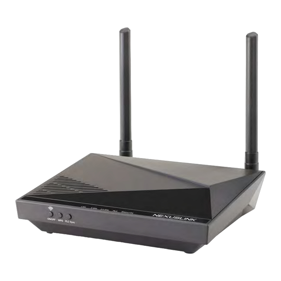
Chapter 1 Introduction NexusLink’s GPL-1200WAC is designed to meet the growing demand for perfect connectivity and coverage across multiple devices connected concurrently throughout the home. The G.hn Powerline Wi-Fi extender allows users to take Wi-Fi with them anywhere throughout the home or backyard and enjoy a seamless wireless experience. -
Page 7: Chapter 2 How To Install Gpl-1200Ac
Chapter 2 How to Install GPL-1200WAC (A) Understanding the AC1200 G.hn Powerline Adapter LED Descriptions are Listed Below Gigabit On/Off Ethernet Power Port Button WiFi Adapter Power Power Port Reset Button Pairing On/Off Press for more than10 Button Button seconds for Factory Reset. - Page 8 (B) Creating a New G.hn Network Plug a GPL-1200* unit into the power outlet closest to the Network Device (Modem, Router). Do not plug the adapter into a power strip or surge protector, as network performance could degrade significantly. *NOTE: It is suggested that you use the GPL-1200 as the primary connection to the Network Device, however the GPL-1200 can be replaced by another G.hn Powerline Adapter.
- Page 9 (C) Adding to an Existing G.hn Network Plug the GPL-1200WAC into the power outlet closest to the location you want to add wireless and/or near an Internet-Enabled Device you would like to directly connect to the adapter. The PLC Indicator should light up.
- Page 10 Go to Section G. (F) Setup of Wireless Devices via WPS (WiFi Protected Setup) Press and hold the “WPS” Button for more than 2 seconds on the GPL-1200WAC to activate its WPS. The GPL-1200WAC’s WiFi Indicators should flash to indicate a WPS connection is in progress.
- Page 11 WiFi is not enabled. You can turn on both indicators, (i.e. enable WiFi) by pressing the “WiFi” Button on the front of the device. You can also login to the GPL-1200WAC Web Interface and enable WiFi (5GHz only). Please refer to section 6.5 of the User Manual for additional details.
- Page 12 PLC Indicator should light up. If the PLC Indicator does not light up, it may indicate the existing G.hn network is secure and you have to pair the GPL-1200WAC to it in “secure mode.” To do so, press the “Config" Button on the GPL-1200 for 2 seconds (Holding for more than 4 seconds will clear the security key and require a re-pairing).
-
Page 13: Chapter 3 Led Indications
Chapter 3 LED Indications COLOR MODE DESCRIPTION The current connection (line rate) is more than 40 Mbps Green Blink System rebooting The current connection (line rate) is more than 20 Orange Mbps and less than 40 Mbps (1). The current connection (line rate) is between 1 and 20 Mbps per second) (2). -
Page 14: Chapter 4 Button Functions
BUTTON TO PUSH DESCRIPTION ENCLOSURE FUNCTION BUTTON Press the power button once to turn the GPL-1200WAC On. Power the device On/Off On and Off Press the power button once to turn the GPL-1200WAC Off. Press more than 2 seconds (... -
Page 15: Chapter 5 Wireless System And Network Setup
IP address automatically (dynamic IP address). GPL-1200WAC gets a dynamic IP address from Modem/Broadband Router/Home Gateway that it is connected to by default. However, the current IP info of GPL-1200WAC would be displayed at the Modem/Broadcom Router/Home Gateway. -
Page 16: Connecting To Web Management Interface
5.2 Connecting to Web Management Interface All functions and settings for the Wi-Fi AP of GPL-1200WAC must be configured via the web management interface. Please start your web browser, and input ‘192.168.0.5’in the address bar, then press the ‘Enter’ key. The following will be displayed: Please input user name and password in their respective fields, default user name is ‘root’, and default password is ‘12345’, then press the Login button, to view the web... -
Page 17: View System Information
5.3 View System Information The system information is on the left-side of the web page as shown below. - Page 18 Description 2.4GHz Network Displays 2.4GHz AP status, Channel, MAC, BSSID and SSID string. 5GHz Network Displays 5GHz AP status, Channel, MAC, BSSID and SSID string. Common WiFi and G.hn Image version information. WiFi Image version: GPL-1200WAC-WLAN-684125CTU-C01_R01 G.hn Image version: GPL-1200WAC-PLC-64R39873CTU-C01_R01...
-
Page 19: Network Settings
Here are descriptions of every item: Heading Description MAC address This option will list the Wireless stations connected to the GPL-1200WAC at the 2.4G or 5GHz Interface. Rate (MCS) MCS# on the wireless interface with the station. Bandwidth Bandwidth, 20/40MHz for 2.4GHz, 20/40/80MHz for... -
Page 20: Network Timing
5.6 Network Timing This page allows you to set the local time zone for TR069 management. Heading Description Enable NTP You can decide to set up NTP client by clicking checkbox. Primary NTP Server Input the Primary NTP Server, for example: us.pool.ntp.org, etc. -
Page 21: Access Policy
5.7 Access Policy This page allows you to set the Access Policy for a specific MAC address. Here are descriptions of every item: Heading Description Policy: This option will allow/reject the list of wireless stations. Add a station MAC MAC format is XX:XX:XX:XX:XX:XX A maximum of 32 entries can be configured. -
Page 22: Administration
Click this button to change the password (Only for “admin” Change Password account) Download Log Files Reserved for debugging purpose Click this button to reset all the settings of GPL-1200WAC Restore Defaults to their factory defaults (Wi-Fi & G.hn PLC) System Reboot Click this button to restart the GPL-1200WAC... -
Page 23: Monitor
5.9 Monitor This page shows the statistics on LAN, 2.4G & 5G interfaces. 5.10 Logout Log out from the web management. -
Page 24: Chapter 6 Wireless Configurations
Chapter 6 Wireless Configurations 6.1 2.4G Wireless Settings This page allows you to configure the basic settings for the 2.4GHz interface of the access point. Here are descriptions of every setup item: Heading Description Wireless Mode 802.11b/g legacy: auto selection of 802.11b/g. 802.11b/g/n: auto selection of 802.11b/g/n Broadcast SSID Decide if the wireless power line access point will... -
Page 25: Multiple Bss
20MHz : lower performance but less interference. 40MHz : Auto 40/20MHz(automatically select based on interference level) WMM (Wi-Fi Multimedia) technology, can improve the performance of certain network applications, like audio/video streaming, network telephony (VoIP), and others. When you enable the WMM function, the power line access point will define the priority of different kinds of data, to give higher priority to applications which require an instant response. -
Page 26: G Security Settings
6.2 2.4G Security Settings This page allows you to configure the Security Settings for 2.4Ghz interface of the access point. Click the Apply button to save your settings. Here are descriptions of every setup item: Heading Description Wireless Interface Select the interface that you want to configure from the SSID or the BSSs you have added. -
Page 27: G Wps Settings
6.3 2.4G WPS Settings This page allows you to configure the WPS Settings for 2.4Ghz interface of the access point. Wi-Fi Protected Setup allows that each time you want to set up a connection, there is no need to select the encryption mode and enter the encryption password. Heading Description Select to Enable/Disable WPS from the drop-down... -
Page 28: G Air Time Management
6.4 2.4G Air Time Management This page allows you to configure the setting for Air Time Management of the 2.4GHz Access Point. 6.4.1 2.4Ghz Air Time Management This part shows the Statistics of BSS, Station or throughput. Heading Description Per BSS Statistics Displays each BSS’s statistics Per Station Statistics Displays each Station’s statistics... -
Page 29: Configuration
6.4.2 Configuration This part allows you to set up the Air Time Management, select the Scheduler Algorithm and whether show throughput statistics or not. Heading Description Air Time Select to Enable/Disable Air Time Management from the Management drop-down menu. Scheduler Algorithm Select to No Fairness(Round Robin)/Fairness/Weighted Fairness Scheduler Algorithm from the drop-down menu, No Fairness(Round Robin) :... -
Page 30: Wireless Settings
6.5 5G Wireless Settings This page is to configure basic settings for the 5GHz interface of the access point. Here are descriptions of every setup item: Heading Description Enable 5Ghz Radio Tick to enable 5GHz radio. Broadcast SSID Decide if the wireless power line access point will broadcast its own SSID or not. -
Page 31: Multiple Bss
performance of certain network applications, like audio/video streaming, network telephony (VoIP), and others. When you enable the WMM function, the power line access point will define the priority of different kinds of data, to give higher priority to applications which require an instant response. -
Page 32: Security Settings
6.6 5G Security Settings This page allows you to configure the Security Settings for the 5Ghz interface of the access point. Here are descriptions of every setup item: Heading Description Wireless Interface Select the interface that you want to configure from the SSID or the BSSs you have added. -
Page 33: Wps Settings
6.7 5G WPS Settings This page allows you to configure the WPS Settings for the 5Ghz interface of the access point. Wi-Fi Protected Setup means that each time you want to set up a connection, there is no need to select the encryption mode and enter the encryption password. Heading Description Select to Enable/Disable WPS from the drop-down... -
Page 34: Air Time Management
6.8 5G Air Time Management This page allows you to configure the setting for Air Time Management of 5GHz Access Point. 6.8.1 5Ghz Air Time Management This part shows the Statistics of BSS, Station or throughput. Heading Description Per BSS Statistics Displays each BSS’s statistics Per Station Statistics Displays each Station’s statistics... -
Page 35: Configuration
6.8.2 Configuration This part allows you to set up the Air Time Management, select the Scheduler Algorithm and whether to show throughput statistics or not. Heading Description Air Time Select to Enable/Disable Air Time Management from the Management drop-down menu. Scheduler Algorithm Select to No Fairness(Round Robin)/Fairness/Weighted Fairness Scheduler Algorithm from the drop-down menu,... -
Page 36: Chapter 7 G.hn/Powerline Setup
Chapter 7 G.hn/Powerline Setup 7.1 Configure STATIC IP MODE In static IP mode, you assign IP settings to your PC manually. Follow these steps to configure your PC IP address to use subnet 10.10.1.x. NOTE: The following procedure assumes you are running Windows. However, the general steps involved are similar for most operating systems (OS). -
Page 37: Logging In
7.2 Logging In Perform the following steps to login to the web user interface. STEP 1: Start the Internet browser and enter the default IP address for the device in the Web address field. For example, if the default IP address is 10.10.1.69, type http://10.10.1.69 STEP 2: A dialog box will appear, such as the one below. -
Page 38: Hn Interface
7.3 G.hn Interface... -
Page 39: Basic Configuration
7.3.1 Basic Configuration • MAC Address Displays the MAC address of the device. • Device ID Device ID of this node. • Domain Name string of all nodes in the network. • Force node Type force the modem to have a particular role (END POINT or DOMAIN MASTER) •... -
Page 40: Ip Interface
7.4 IP Interface... -
Page 41: Ip Config
7.4.1 IP config In the IP configuration tab of one G.hn node, the IPv4 and IPv6 settings can be read and changed. IPv4 subsection: • DHCPv4 enabled: in the case of choosing ”NO" IP configuration in the following parameters, the IPv4 Address, Subnet Mask, Default Gateway and DNS should be configured;... -
Page 42: Ethernet Interface
7.5 Ethernet Interface The Ethernet table shows the coverage & Info of the Ethernet interface; including Interface, Speed, Duplex, Interface Type, Mode, Internal PHY & Link. Powersaving This function is not supported in this firmware release. -
Page 43: Device Interface
7.6 Device Interface 7.6.1 Hardware information In this tab, basic information such as MAC Address and Serial Number of the selected node is shown. 7.6.2 Software information Shows the FW version and system uptime. -
Page 44: Security
7.6.3 Security The nodes in the network: to change the configuration password string from the default ("admin") to another; decided by the user. 7.6.4 SW update Current loaded firmware version is shown. Any flash section can be upgraded; the first flash section should be selected and after clicking on the "OK"... -
Page 45: Multicast Interface
7.7 Multicast Interface 7.7.1 MCAST Configuration In the MCAST Configuration tab of "My Network", IGMP snooping and MLD features can be enabled or disabled. Also, IGMP multicast IP addresses ranges which the G.hn PLC network will sniff; can be configured. •... -
Page 46: Q Osmenu
7.8 QoS menu 7.8.1 QoS Configuration In the QoS configuration tab, the packet classifier can be managed to define a QoS rule for incoming Ethernet traffic, and assign a priority to be used in the G.hn network. Press the “Ok" button for loading the newly configured settings: •... - Page 47 • Packet detection 1: first packet detection rule can be configured (offset, bitmask and pattern). Packets which accomplish it will be sent to the classification module. • Packet detection 2: if second packet detection is also enabled, both, first and second detection criteria must be accomplished to pass packets to the classification module.
- Page 48 Example If QoS criterion: 802.1p, all other options are grayed out, and follow the QoS rules below. According to G.9960 specs, the priority mapping recommended by [IEEE 802.1D] subclause 7.7.3 is presented in Table III.1. for four priority queues. Priority Acronym Traffic Types 0 (Third)
-
Page 49: Vlan Interface
7.9 VLAN Interface 7.9.1 VLAN Configuration In the VLAN Configuration tab of one G.hn node, a VLAN tag can be added or removed per interface. Also, removing a tag at egress per interface can be also enabled or disabled: • Enable VLAN Configuration: Select No from the drop down menu to disable completely the VLAN functionality, removing all tags. -
Page 50: Hn Spectrum Interface
7.10 G.hn spectrum Interface 7.10.1 Notches In this tab a table with all configured Notches of selected node will be shown. The table is composed of next columns for every notch: Notch Number, Type of notch, Start Frequency (KHz), Stop Frequency (KHz), Depth (in dB). The first 13 notches (Regulation) are Read Only, RO, in the system and they can be neither removed nor modified. -
Page 51: Log File Interface
7.11 Log file Interface 7.11.1 Log File In the Log File configuration the following settings can be read, and changed by clicking on the corresponding "OK" button for the selected node: • Enable Log File set to YES for enabling Log File functionality in the node and set to NO for disabling it. -
Page 52: Advanced Interface
7.12 Advanced Interface Broadcast suppression: In this tab the broadcast suppression feature can be managed. Broadcast traffic higher than the selected value will be dropped. Hardware Reset: Click on this button to perform a reboot in the node. Factory Reset: Input the password: betera and click the OK button to perform a factory reset.
Need help?
Do you have a question about the GPL-1200WAC and is the answer not in the manual?
Questions and answers