Table of Contents
Advertisement
Quick Links
IMPORTANT NOTE: For the most up-to-date version of this manual, please visit www.h2fl ow.net/product-literature
ACUFLOW™
FLOW METER
Operating Manual
North American version (English)
Tel: 888-635-0296 (Toll Free)
digital
digital
www.h2fl ow.net
(+1) 419-841-7774 (International)
OR
English
Rev.1.0
01/2021
Advertisement
Table of Contents

Subscribe to Our Youtube Channel
Related Manuals for H2flow ACUFLOW digital


Summary of Contents for H2flow ACUFLOW digital
- Page 1 English Rev.1.0 01/2021 IMPORTANT NOTE: For the most up-to-date version of this manual, please visit www.h2fl ow.net/product-literature ACUFLOW™ digital digital FLOW METER Operating Manual North American version (English) www.h2fl ow.net Tel: 888-635-0296 (Toll Free) (+1) 419-841-7774 (International)
-
Page 2: Table Of Contents
Display Features ....................16 Troubleshooting ....................17 Environmental ....................... 19 Standards & Approvals ..................19 NSF 50 Accuracy Certification ..............20 Specifications ......................21 Warranty ........................22 Notes ......................... back cover www.h2flow.net • Tel: 888-635-0296 (Toll Free) (+1) 419-841-7774 (International) -
Page 3: Description
Even with the ability to install AcuFlow in tight spaces and with almost zero straight pipe requirements, it can sometimes be difficult to install the device in a location that makes it easy to read. AcuFlow Digital solves this problem by allowing you to install a Digital readout in a user-accessible location. -
Page 4: What's Included
4. what’s included AcuFlow Digital model AF-D / AF-D-PM includes: Fig 1.0 100-240VAC to Fig 1.1 NEMA 4X enclosure Fig 1.2 Sensor with standard Fig 1.3 x2 extended length 12VDC Power Supply (with with pre-mounted Display cable lid screws interchangable international... -
Page 5: Dimensions
November 2020. This section covers two scenarios for installing the AcuFlow Digital system: a) Install AcuFlow Digital to a new OR existing AcuFlow unit for 1.5”/DN40, 2”/DN50, or 2.5”/DN65 pipe. If this section applies to you, please refer to Installation section 6.1 before proceeding to Installation section 6.3. -
Page 6: Installation
6.1. Replacing the fl apper & indicator assembly in 1.5” (DN40), 2” (DN50) and 2.5” (DN65) installations For the AcuFlow Digital (AF-D) to function on AcuFlow models AF-15, AF-C-M-DN40, AF-2, AF-C-M-DN50, AF-25, and AF-C-M-DN65, it will be necessary to replace the Flapper and its attached red indicator with the one provided in the AF-D packing box (see Fig.1.4 on page 4) - regardless of whether the AcuFlow unit itself is new or already installed. - Page 7 6.2. Installing AcuFlow Digital to an existing (pre- January 2021) 3”(DN80) or 4” (DN100) AcuFlow Remove the screws from the existing lid of the AcuFlow unit and remove the lid assembly. 2. It is not uncommon for the AcuFlow lid to be retained by a vacuum suction after the 8 screws have been removed.
- Page 8 Fig.2.4). 4. Place the 2 extended screws provided with your AcuFlow Digital (Fig.1.3 on page 4) in the holes for the sensor and using a hand Phillips-head screwdriver, slowly tighten the screws. Do not fully tighten either screw before proceeding to the next, i.e., pull them down slowly, multiple times to avoid stressing and cracking the sensor.
-
Page 9: Wiring
8. wiring Power Supply Wiring Sensor Wiring Fig 2.6 Fig 2.7 www.h2flow.net • Tel: 888-635-0296 (Toll Free) (+1) 419-841-7774 (International) -
Page 10: Output
9. output Auxiliary Relay External 4-20 mA Wiring Equipment Connection Fig 2.9 Auxiliary Relay Wiring COIL Fig 2.8 Fig 3.0 www.h2flow.net • Tel: 888-635-0296 (Toll Free) (+1) 419-841-7774 (International) -
Page 11: Programming
AF-2-U 2” Fig 3.2 (left) The Fig 3.3 (left) DIP default setting for switch number 1 set the DIP switches (all to the ON position. switches set to the OFF position). www.h2flow.net • Tel: 888-635-0296 (Toll Free) (+1) 419-841-7774 (International) -
Page 12: Operation
11. operation After setting the DIP Switches to reflect the AcuFlow model and Pipe Size employed in your application, the AcuFlow Digital is ready to use. No calibration or further settings are required. However, by default, the AcuFlow Digital readout will display the flow rate in US GPM and the Turnover Rate will show --- (indicating that this function is not activated). - Page 13 With the Configurator program still open, connect the Display to your PC using the Type A to Type B cable that was delivered with your AcuFlow Digital (Fig 1.5). The AcuFlow Digital screen should display the text ‘US.b’, and the Configurator should now look like Fig.3.5, below. Click on the ‘Configure APM’ button.
- Page 14 advanced setup cont. You should now see a screen that looks like the one below (Fig. 3.6): In this screen, you can program: • The unit of measurement in either US GPM (default), LPM, or M • If being installed to a swimming pool or tank application, then the turnover rate by inserting the volume Please do not change any other values.
-
Page 15: Auxiliary Relay
13. auxiliary relay (optional kit) The Auxiliary Relay option is a valuable feature that allows the AcuFlow Digital user to control external devices such as Heater and Chemical Feeders at user-defi ned fl ow rates. For example, you may want to control the Chemical Feeder to operate only above 20 GPM. -
Page 16: Display Features
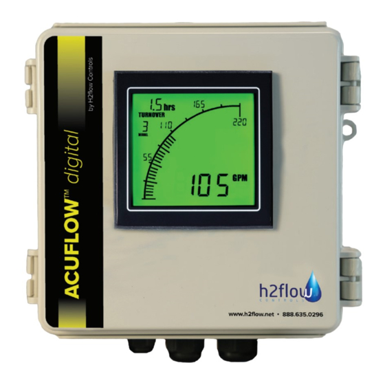
14. display features The AcuFlow Digital Display comprises certain standard features as well as user-defi ned parameters / adjustments. Standard features include a Digital and Bar Graph reading of the measured fl ow rate. The user has the option to program the Unit of Measurement to be displayed in either US GPM (default), LPM or M /hour. -
Page 17: Troubleshooting
14. display features cont. On all AcuFlow Digital installations for 8-inch AcuFlow units, please note that the text ‘X10’ will appear above the flow reading at all times. See the below examples (Figs. 3.7 & 3.8) and instructions on how to properly read these flow rates: Note the ‘X10’... - Page 18 Digital Display is reading • Check that the DIP switch settings applied in ‘Programming’ section, correcly related to a flow rate that is the AcuFlow model being used. If applied correctly, please contact H2flow for further significantly different to guidance. the AcuFlow Turnover rate appears to •...
-
Page 19: Environmental
16. environmental See specifi cation section for environmental operating conditions. For product disposal, follow all local environmental requirements mandated for plastic and electronic equipment. 17. standards & approvals Display & Sensor NSF 50 certifi ed, (indoor use only) Power Supply UL, cUL, CE www.h2fl ow.net •... -
Page 20: Nsf 50 Accuracy Certification
The accuracy of AcuFlow Digital has been independently certified by NSF to the NSF 50 Standard for Flow Meters. At the time of printing, AcuFlow Digital is the only digital flow meter in the world to have been certified to this rigorous standard. -
Page 21: Specifications
Relay Coil ................12VDC (sourced and controlled by the Display) Analog Output (4-20mA) Scaled to ................4 mA = zero flow, 20 mA = max flow rate limit of installed AcuFlow Output Format ..............Voltage sourced from AcuFlow Digital Display Maximum Load ..............250 ohms Accuracy Average Flow Rate Accuracy ......... -
Page 22: Warranty
AcuFlow Digital sensor or AcuFlow lid due to the over-tightening of lid screws, damage to the AcuFlow Digital LCD display screen due to misuse or excessive exposure to chemicals, use or installation in an outdoor, wet or ‘washdown’... - Page 23 4 above, when the customer will be liable for the full cost of the repair (parts and labor) plus all carriage and insurance costs to and from H2flow Controls Inc’s premises.
-
Page 24: Notes
21. notes H2fl ow Controls, Inc., 3545 Silica Road, Unit F, Sylvania, OH 43560 U.S.A. Tel: 888-635-0296 (Toll Free) (+1) 419-841-7774 (International) • Fax: 419-517-9900 For international sales and service, please visit our website: www.h2flow.net AF-D-Release 1.0 01/2021 English...
Need help?
Do you have a question about the ACUFLOW digital and is the answer not in the manual?
Questions and answers