Table of Contents
Advertisement
Quick Links
Advertisement
Table of Contents

Subscribe to Our Youtube Channel
Related Manuals for H2flow FlowVis Digital


Summary of Contents for H2flow FlowVis Digital
- Page 1 English Rev.1.1 10/2019 FlowVis® digital IMPORTANT NOTE: For the most up-to-date version of this manual, please visit www.h2fl ow.net/product-literature Operating Manual (EN) www.h2fl ow.net • Tel: 888-635-0296 (Toll Free) (+1) 419-841-7774 (International)
-
Page 2: Table Of Contents
Operation ........................ 8 Advanced Setup ....................9 Auxiliary Relay ...................... 11 Display Features ....................13 Troubleshooting ....................13 Environmental ....................... 14 Standards & Approvals ..................14 Specifications ......................15 Warranty ........................16 www.h2flow.net • Tel: 888-635-0296 (Toll Free) (+1) 419-841-7774 (International) -
Page 3: Description
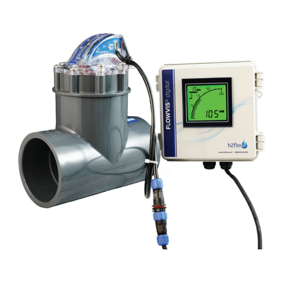
Even with the ability to install FlowVis in tight spaces and with almost zero straight pipe requirements, it can sometimes be difficult to install the device in a location that makes it easy to read. FlowVis Digital solves this problem by allowing you to install a Digital readout in a user accessible location. -
Page 4: What's Included
(if purchased) and cable mounted Display and cable glands what’s included Retrofi tting FlowVis Digital to existing FlowVis installation: Fig 1.4 120VAC to 12VDC Fig 1.4 120VAC to 12VDC Fig 1.5 NEMA 4X Fig 1.6 Sensor with Fig 1.7 x2 extended length... -
Page 5: Dimensions
For product dimensions, please refer to the images below (Fig 2.2 & 2.3). Please note: Dimensions are the same for FlowVis Digital indoor and outdoor models. *Cable glands supplied; not pictured below; please refer to Fig 1.2 on pg.4. Cable glands supplied; not pictured below; please refer to Fig 1.2 on pg.4. -
Page 6: Wiring
Retrofitting FlowVis Digital to an existing FlowVis installation Check the contents to make sure that they comply with section titled ‘Retrofitting FlowVis Digital to Existing FlowVis Installation’, on page 4 of this document. Remove two FlowVis lid screws that will align with the hole mounting tabs on the sensor... -
Page 7: Output
4-20 mA Auxiliary Relay Fig 2.6 Fig 2.7 Auxiliary Relay Connections Fig 2.8 www.h2flow.net • Tel: 888-635-0296 (Toll Free) (+1) 419-841-7774 (International) -
Page 8: Programming
After setting the DIP Switches to reflect the FlowVis model and Pipe Size employed in your application, the FlowVis Digital is ready to use. No calibration or further settings are required. However, by default, the FlowVis Digital readout will display the flow rate in US GPM and the Turnover Rate will show --- (indicating that this function is not activated). -
Page 9: Advanced Setup
Although FlowVis Digital will function as a flow meter without further steps, there are several very useful features that can be accessed via the ‘advanced setup’ procedures. These features comprise: • Display of the pool turnover rate •... - Page 10 Step 2 - Programming the advanced features of the FlowVis Digital Display Connect the Display to your PC using the Type A to Type B cable that was delivered with your FlowVis Digital Open the FlowVis Configurator Program to display the following screen: www.h2flow.net •...
-
Page 11: Auxiliary Relay
Step 5 - Enabling a Display and Auxiliary Relay Alarm FlowVis Digital enables the user to program the Display to either flash, change color, or both, whenever a flow rate condition is reached. The desired condition is set as a flow rate value that is either: Above the value set 2. - Page 12 auxiliary relay (optional kit) cont. Installation (internal) Secure Relay by removing adhesive backing tape 2. Attach pre-made blue wire to terminal 1 on Relay 3. Attach pre-made red wire to terminal 0 on Relay 4. After removing protective fi lm, attach Cable Pad to rear of hinged door in location shown 5.
-
Page 13: Display Features
fl ow rate troubleshooting FlowVis Digital has been designed to be an easy to install, accurate and reliable addition to the renowned FlowVis fl ow meter. However, should an unexpected problem occur, please refer to the following Troubleshooting Guide. As always, please feel free to contact us with any questions or concerns. Tel: 888.635.0296... -
Page 14: Environmental
troubleshooting cont. Observation Solution Digital Display not • Is this a retrofi t to an existing FlowVis? If yes, did you install a new lid assembly that is illuminated (continued ‘Digital’ compatible? If no... from previous page) • Contact H2fl ow for further guidance Digital Display is reading •... -
Page 15: Specifications
Relay Coil ................12VDC (sourced and controlled by the Display) Analog Output (4-20mA) Scaled to ................4 mA = zero flow, 20 mA = max flow rate limit of installed FlowVis Output Format ..............Voltage sourced from FlowVis Digital Display Maximum Load ..............250 ohms Accuracy Flow Rate Accuracy ............ -
Page 16: Warranty
Failure to present this evidence may limit H2fl ow Controls Inc’s obligations under this warranty. THIS WARRANTY IS GIVEN BY H2FLOW CONTROLS INC. IN LIEU OF ANY OTHER WARRANTIES, EXPRESSED OR IMPLIED, INCLUDING BUT NOT LIMITED TO ANY IMPLIED WARRANTY OF MERCHANTABILITY, NON INFRINGEMENT OR FITNESS FOR A PARTICULAR PURPOSE.
Need help?
Do you have a question about the FlowVis Digital and is the answer not in the manual?
Questions and answers