
Subscribe to Our Youtube Channel
Related Manuals for H2flow FLOWVIS


Summary of Contents for H2flow FLOWVIS
- Page 1 FlowVis Flow Meter ® Instruction Manual H2fl ow Controls, Inc. H2fl ow Controls, Inc. 3545 Silica Road Unit F Sylvania, OH 43560 Tel: 888-635-0296 Fax: 419-517-9900 E-mail: sales@h2fl ow.net www.h2fl ow.net...
-
Page 2: Table Of Contents
H2fl ow will not be responsible for replacing a FlowVis® unit if it is apparent that the damage has occurred due to a high concentration of acidic compounds or other concentrated chemical mixtures that are... -
Page 3: Description
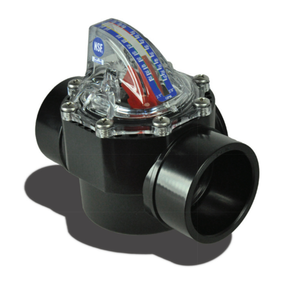
Calibrated Scale Flow 3.0 NSF 50 FlowVis® model FV-C has been tested and certifi ed as a Flow Meter to NSF 50. 4.0 NSF 50 Mark Models certifi ed to NSF 50 will comprise the Mark as shown in the image to the right. -
Page 4: Applications
When purchased as a complete Check Valve & Flow Meter combination, a copy of these instructions will be included with the FlowVis® packaging. If a FlowVis® retrofi t kit has been purchased, it is the installer’s responsibility to ensure that the Check Valve has been installed correctly and does not violate any local or federal codes relating to Check Valves. -
Page 5: 8.0 Installation
Normal plumbing procedures such as cleaning, priming and gluing of fi xtures should be followed in order to avoid leaks. Unlike other fl ow meters, FlowVis® is not eff ected by fl ow stream disturbances caused by its proximity to pumps, elbows, tees, valves etc. FlowVis® does not require specifi c straight pipe lengths before or after its point of installation and can be installed close to, or even adjacent to other plumbing fi ttings. -
Page 6: Operation
NOTE: Slowly move your head in this direction to the point where the leading edge of the indicating arm is not visible. 10.0 MAINTENANCE Although FlowVis® is designed to be maintenance-free, periodic checks should be made to the following: Item Check for Remedy ‘O’ ring seal Check for leaks Replace ‘O’... -
Page 7: 11.0 Specifi Cations
FlowVis® - INSTRUCTION MANUAL Page 7 11.0 SPECIFICATIONS Materials used: Item Material / Comments Valve Cover Screws Stainless Steel Valve Body CPVC Plastic, Chlorine, Acid resistant Valve Lid Poly Carbonate (PC), Chlorine, Ozone resistant Calibrated Spring Stainless Steel Pivot Pin Stainless Steel ‘O’ Ring Silicone-Lubricated Elastomer Operation: Function... -
Page 8: 12.0 Warranty
4 above, when the customer will be liable for the full cost of the repair (parts and labor) plus all carriage and insurance costs to and from H2flow Controls Inc’s premises.
Need help?
Do you have a question about the FLOWVIS and is the answer not in the manual?
Questions and answers