
Related Manuals for H2flow FaraMag FM750


Summary of Contents for H2flow FaraMag FM750
- Page 1 English Rev.1.1 06/2021 FaraMag™ FM750 Mag Meter IMPORTANT NOTE: For the most up-to-date version of this manual, please visit www.h2fl ow.net/product-literature Operating Manual (EN) www.h2fl ow.net...
- Page 2 table of contents General Information ............3 Product Performance and Indicators ......32 Description ..............3 Basic Functions ............32 Unpacking and Inspection ........4 Special Functions ............32 Normal Working Conditions ........32 Technical Data ..............5 Connection Method with Sensor ......32 Sensor Matching Requirements ......32 Measurable Flow Ranges ..........
-
Page 3: General Information
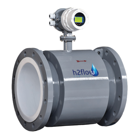
Description The FaraMag FM750 utilizes the electromagnetic principle to measure the fl ow volume of conductive liquids and slurry in a closed pipe. This technology is widely used in power, oil and gas, chemical and petrochemical, coal, metallurgy, mineral, paper, water, wastewater, food and beverage, pharmaceutical and other industries. -
Page 4: Unpacking And Inspection
Unpacking and Inspection Upon receipt, examine your meter for any visible damage. The meter is a precision measuring instrument and should be handled with care. Remove the protective plugs and caps for a thorough inspection. If any items are damaged or missing, please contact us immediately. -
Page 5: Technical Data
1500:1, flow rate <15m/s Structure Type Integral Type, Remote Type, Submersible Type, ex-proof Type Connection Type Flange Type / Clamp Type (optional on certain models) Protection Grade NEMA4 (IP65), NEMA 6 (IP67), NEMA 6P (IP68) Product Standard JB/T 9248-1999 Electromagnetic Flowmeter www.h2flow.net... - Page 6 83126.5416 318.6896 478034.3891 1600 72.3823 108573.4421 403.3413 605012.2739 1800 91.6088 137413.2627 497.9523 746928.7331 2000 113.0973 169646.0033 602.5226 903546.0122 2200 136.8478 205217.6640 717.0517 1075577.3760 2400 162.8602 244290.2448 841.5388 1262308.0460 2600 191.1343 286701.4020 2800 AVAILABLE UPON REQUEST AVAILABLE UPON REQUEST 3000 www.h2flow.net...
-
Page 7: Model Selection
*Standard cable length is 10 meters for remote type. Cable length is customizable. Power Supply: 120VAC-230VAC 11-40VDC 11-40VDC with 120VAC-230VAC converter (UL listed) 3.6V Lithium Battery Converter Model: Pulse+4-20mA, RS485 Pulse+4-20mA, RS485, HART Pulse+4-20mA, RS485, Profibus DP Pulse+4-20mA, RS232 GPRS Wireless Communication www.h2flow.net... -
Page 8: Installation Considerations
• Avoid all pipe locations where the flow is pulsating, such as in the outlet side of piston or diaphragm pumps. • Avoid locations near equipment producing electrical interference , such as electric motors, transformers, variable frequency drives, etc. www.h2flow.net... -
Page 9: Special Notice
• Install the meter with enough room for future access for maintenance purposes. • The magnetic meter isolating liner, whether it is PTFE or Rubber, is not intended to be used as gasket material. Standard gaskets (not provided) should be installed to ensure a proper hydraulic seal. When installing the gaskets, make sure they are properly centered to avoid fl ow restriction or turbulence. - Page 10 Stray AC or DC currents through the fluid or instrument can produce noise signals that may in turn interfere with the relatively low flow signals generated in today’s modern pulsed DC mag meter. H2flow Controls provides a variety of elements (ground straps, ground electrodes, ground rings) and directions for the standard grounding of the mag meter.
- Page 11 4 x 14 4 x 14 4 x 18 4 x 18 4 x 18 4 x 18 8 x 18 8 x 18 8 x 18 8 x 22 12 x 22 12 x 22 12 x 22 www.h2flow.net...
- Page 12 4 x 15 98.5 4 x 15 120.5 4 x 19 139.5 4 x 19 152.5 4 x 19 190.5 8 x 19 8 x 23 241.5 8 x 23 298.5 8 x 23 12 x 25 12 x 25 www.h2flow.net...
- Page 13 6. converter connection Terminal Wiring and Marking (Compact Type) TERMINAL BLOCK Terminal Description DOUT - Alarm Output Ground DOUT + Alarm Output Positive POUT - Pulse/Frequency Output negative POUT + Pulse/Frequency Output positive 4-20mA + 4-20mA positive 4-20mA - 4-20mA negative RS485 + Communication input (RS485A) RS485 -...
- Page 14 The excitation current line adopts a two-core insulated rubber flexible cable, and the recommended model is RVVP2*0.3mm². The length of the excitation current line is the same as the length of the signal cable. When using STT3200 dedicated cable, the excitation cable and signal cable are combined into one. www.h2flow.net...
- Page 15 6.3.3 Grounding Requirements for Converter Installation The ground terminal of the converter housing should be connected to the earth with a grounding copper wire not less than 1.6mm². The grounding resistance from the converter case to the ground should be less than 10Ω.
- Page 16 Converter Terminal Fig.6.4.2a Power Supply connected to electronic counter (Compact Type) Flow Cumulant Converter Terminal Fig.6.4.2b Inner Power Supply connected to electric counter (Compact Type) Flow Cumulant DC Power Converter Terminal Fig.6.4.2c Power Supply connected to electronic counter (Remote Type) www.h2flow.net...
-
Page 17: Alarm Output Wiring
Upper/Lower Limit Alarm Converter Terminal DC Power Fig.6.4.3 Alarm output wiring 6.4.4 Connection of OC Gate Meter Outside Meter Outside Meter Inside Meter Inside F/P+ F/P- DOA+ DOA- Fig.6.4.4 Connection of OC Gate Fig.6.4.4 Connection of OC Gate (Compact-Type) (Remote-Type) www.h2flow.net... -
Page 18: Setting Parameters
* frequency full range value; • Instrument current output value = (measured flow value / measure range of the meter) * current full-scale value + zero point; The pulse output value of the instrument is not affected by the instrument measure range setting. www.h2flow.net... - Page 19 If the “FST” display appears frequently, it is recommended to increase the peak suppression range. 7.1.9 Peak Suppression Time This parameter selects the peak width time to suppress peak pseudo-signal. This is displayed in units of seconds. www.h2flow.net...
- Page 20 Flow Direction Options If user believes that the fluid direction during commissioning is inconsistent with the design, the connection of the excitation wire or signal wire does not need to be changed. Simply adjust the flow direction setting within the parameters. www.h2flow.net...
- Page 21 When recording, the sensor zero value is the flow velocity value in mm/s, and its signs is opposite to the sign of the correction value. FS = ± O O O O O ± O O O O www.h2flow.net...
-
Page 22: Meter Factor
When the excitation alarm parameter is set to “allow”, if the excitation coil fails, the converter displays SYS, and the terminals DO+ and DO- output high levels. When the excitation alarm parameter is set to “allow output” , if the excitation coil fails, the converter displays SYS, and terminals DO+ and DO- output low levels. www.h2flow.net... - Page 23 When correcting the empty tube range, make sure that there is no fluid in the sensor tube. The empty tube range correction display is as follows. MR = O O 1 0 7 1. O O O O www.h2flow.net...
-
Page 24: Output Setup
59.999m³, 0.001 - 59.999L, 0.001 - 59.999ukg, 0.001 -59.999usg, 0.001 - 59.999kg, 0.001 - 59.999t. Under the same flow rate, if the pulse equivalent is small, the output pulse frequency is high and the accumulated flow error is small. www.h2flow.net... - Page 25 Output Current Test After adjusting the zero and full-scale current outputs, the user can test the output current linearity of the converter with this parameter. Users can set up 0, 20.00, 50.00, 70.00, 99.99 to check the linearity of output current. www.h2flow.net...
-
Page 26: Sensor Setup
Altering this value will effect the accuracy of the flow reading of your meter. 7.4.4 Flow Rate Correction See Appendix I for details. 7.4.5 Sensor Code The sensor code can be used to mark the factory time and number of the matching sensor to coordinate with the setting of the sensor coefficient. www.h2flow.net... -
Page 27: Communication Setup
User Password 1 - 4 Using the level 5 password allows the user to modify the passwords for all levels. Please contact your local representative or H2flow Controls in order to obtain this password. 7.6.2 Instrument Codes 1 and 2 The converter code records the time and serial number of the converter. - Page 28 8. instrument display and operation Keyboard Defi nition and LCD Display (Compact Type) Flow Rate Alarm Indication Flow Unit Flow Direction Flow Velocity (FS) Flow Percentage (FP) IR Window Empty Pipe Ratio (MT) Positive Cumulant (Σ+) Negative Cumulant (Σ-) Right Esc/Down/-1/Return Enter/Up/+1 Left...
- Page 29 Up button: add 1 to the number at the cursor, return to the previous page/screen; Press the Right button to move the cursor clockwise, and press the Left button to move the cursor counterclockwise; When the cursor moves below the Down button, press the button to return to the previous menu. www.h2flow.net...
- Page 30 When the cursor moves below the up button, press the up button to enter the submenu. When the cursor moves below the down button, press the down button to return to the previous menu. 8.1.3 Remote Control Operation Right Left Converter Enter Fig.8.1.3 Defi nition and operation of infrared remote control buttons...
- Page 31 “total reset password”). Press the “shift button” to move the cursor under the “enter button”, an press the “enter button”. When the total reset password automatically becomes “00000”, the reset function of the meter is completed, and the total amount inside the meter is 0. www.h2flow.net...
- Page 32 Sensor signal sensitivity: at a flow rate of 1 m/s, the sensor outputs 150µV - 200µV; For the FaraMag FM750 electromagnetic flow meter converter, four (4) 62.5mA currents are used in the excitation circuit to form 250mA. Each 62.5mA current is controlled by a 20Ω precision resistor. Therefore, the user can choose a different magnitude of the excitation current by changing the number of precision resistors.
-
Page 33: Installation Dimension Drawing
Installation Dimension Drawing ф 116mm / 4.57” ф 80mm / 3.15” ф 64mm / 2.52” (x8) ф 7mm / 0.28” Figure 9.6a: FM750 Compact Type Shell Dimensions 27mm / 1.06” 24mm / 0.94” 42mm / 1.65” (x4) ф 5mm / 0.12” ф... -
Page 34: Measuring Accuracy
< 4,755 GPM; (< 0.3 m/s) ±0.25% FS 28” - 120” 4,755 - 15,850 GPM; (0.3 - 1 m/s) ±1.0% R (DN700 - DN3000) 15,850 - 237,754 GPM; (1 - 15 m/s) ±0.5% R % FS: Relative Range % R: Relative Measurement www.h2flow.net... - Page 35 Digital Communication Interface and Communication Protocol MODBUS interface: RTU format, physical interface RS485, electrical isolation 1000V; current loop communication interface: support standard current loop communication protocol, configure current loop communication handheld device, can display the measure value online, and modify the instrument parameters. www.h2flow.net...
-
Page 36: Electrical Isolation
For volume flow, the calculation formula is as follows: Example: QL = 0.0007854 x D² x V (L/S) QM = 0.0007854 x D² x V x 10 Here: D- diameter (mm); V- velocity (m www.h2flow.net... - Page 37 If the pipeline fl ow is too large and the pulse equivalent is selected too small, it will cause the pulse output to exceed the upper limit. Therefore, the pulse output frequency should be limited below 500Hz (when the pulse width is 1ms). If the pipeline fl ow is small and the pulse equivalent is selected too large, it will take a long time for the instrument to output a pulse.
-
Page 38: Analog Output
When the flow meter leaves the factory, the manufacturer has calibrated the parameters of the analog output. Under normal circumstances, no further adjustments are required by the user. If an abnormal situation occurs and the user needs to calibrate the analog output, the following operating procedures can be followed. www.h2flow.net... -
Page 39: Analog Output Adjustment
When adjusting the zero point of the instrument, ensure that the fluid in the pipeline is still • Ensure the stable formation of the oxide film of the sensor electrode (the electrode is in continuous contact with the fluid for 48 hours www.h2flow.net... -
Page 40: Alarm Information
Clean the electrode if voltage of DS1 and DS2 > 1V Empty Pipe Alarm If connecting terminals SIG 1, SIG 2, and SIGGND results in the alarm 3. Fluid’s conductivity is not high enough stopping, then the fluid’s conductivity is not high enough for this flow meter. www.h2flow.net... -
Page 41: Appendix I. Non-Linear Correction Function Description
Correction point 5 > Correction point 4 > Correction point 3 > Correction point 2 > Correction point 1 > 0. Correction point 5 (number 5) > correction number 4 > correction number 3 > correction number 2 > correction number 1 > 0 Velocity correction formula: x (Q Qcx: Modified flow rate Qx: Flow rate before correction www.h2flow.net... - Page 42 NOTE: When using non-linear correction, users need to set all correction points and correction numbers according to the setting principle. If no set correction point or correction number provided, the screen will prompt “BUG”, and the non-linear function will not work. www.h2flow.net...
-
Page 43: Appendix Ii. List Of Instrument Menus
Cutoff Alarm En. Velocity Value 3 Rev Total High MT Filter Time Low Flow Cutoff Velocity Point 4 Fluid Density Velocity Value 4 Zero Correction Velocity Point 5 Meter Factor Sensor Code 1 Clear Total Key Sensor Code 2 www.h2flow.net... - Page 44 0 - 5000 Hz Frequency Range Set Count 1 - 5000 Hz Analog Output Select 4-20mA / 4mA Analog Zero CRC Set Count 0.0000 - 1.9999 Analog Range CRC Set Count 0.0000 - 3.9999 Analog Out. Test Set Count 00.00 - 99.99 www.h2flow.net...
- Page 45 Factory Set Year, Month (0 - 99999) Fwd. Total Low User Set 0 - 99999 Fwd. Total High User Set 0 - 99999 Rev. Total Low User Set 0 - 99999 Rev. Total High User Set 0 - 99999 www.h2flow.net...
-
Page 46: Appendix Iii. Passwords
Factory Default Password Level 1 00522 Level 2 03210 Level 3 06108 Level 4 07206 Please consult your local representative Level 5 or H2flow Controls The password level and changeable parameters range is shown in the tables in the preceding section. www.h2flow.net... -
Page 47: Warranty
H2flow Controls Inc. staff to repair or service the product;... - Page 48 H2fl ow Controls, Inc. H2flow Controls, Europe 3545 Silica Road, Unit F Barcelona, Sylvania, OH 43560 Spain U.S.A. Tel: 888-635-0296 Tel: (+34) 609 31 52 82 Fax: 419-517-9900 info@h2floweurope.com sales@h2flow.net www.h2floweurope.com www.h2flow.net FaraMag FM750 Rev.1.1 6/21 English...
Need help?
Do you have a question about the FaraMag FM750 and is the answer not in the manual?
Questions and answers