Table of Contents
Advertisement
Quick Links
Advertisement
Table of Contents

Related Manuals for H2flow FlowVis FVJ-R-15


Summary of Contents for H2flow FlowVis FVJ-R-15
- Page 1 FlowVis® Flow Meter Instruction Manual English...
-
Page 2: Table Of Contents
contents 1. Description ..................3 2. Concept ...................4 3. Resources ..................4 4. Service Repair Kit ................5 5. Markings, Features, Warnings & Safety ........5 5.1 NSF 50 ....................5 5.2 Valve Body Feature.................6 5.3 Tygon Tubing ..................6 5.4 Warnings & Safety ................7 5.5 Indoor / Outdoor Rating ..............7 6. -
Page 3: Description
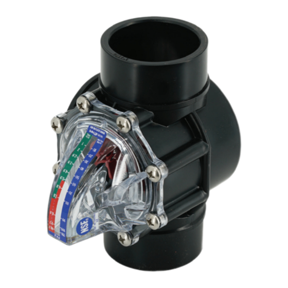
1. description FlowVis® is a revolutionary, patented solution for accurate and reliable fl ow and velocity rate measurement in fresh water applications such as swimming pools, spas, fountains, water features, irrigation systems, ground water applications, well water and solar systems. A FlowVis® model also exists for Flotation Tanks and where the Fig.1.0: FV-15;... -
Page 4: Concept
2. concept As fl ow increases, the fl apper moves forward toward its fully open position. The fl apper’ s angular position is directly related to the fl ow rate through the valve body / tee / pipe. A calibrated scale on the valve’ s lid provides a highly accurate reading of the fl ow rate and velocity. -
Page 5: Service Repair Kit
4. service repair kit Service repair kits are available for all models. FV-SK for all 1.5”, 2”, and 2.5” models, comprising: • 1 x o-ring • 1 x spring • 1 x fl apper and indicator arm (for all models except FV-C-S, and FV-C-Saline) •... -
Page 6: Valve Body Feature
5.2 Valve Body Feature On the side of the valve body that is used for the 1.5”, 2”, and 2.5” models, you may notice the feature shown in Fig.1.4. Note that models with valve bodies produced aft er mid-2022 as well as all models with tees and saddle clamps do not possess this feature): This feature has no functionality relating to the operation of the FlowVis and is... -
Page 7: Warnings & Safety
5.4 Warnings & Safety VGBA WARNING The Virginia Graeme Baker Pool & Spa Act requires that all public swimming pools & spas having a single main drain or multiple drains that are 3 feet or less (center to center) from each other be fi tted with a backup anti-entrapment system. -
Page 8: Models & Specifications
● ● FV-8 ● ● FV-8-L FV-15-U ● ● ● ● ● ● FV-2-U ● ● ● FV-C-S FV-C-S-L ● ● ● ● ● ● FV-C-Saline ● ● ● FV-C-L-Saline ● ● ● FV-C-HF-S Models & Specifications H2flow Controls FlowVis®... - Page 9 ● ● 2271-6814 ● ● ● ● 10-90 ● ● ● ● 10-110 ● ● ● 30-110 ● ● ● 110-400 ● ● ● 20-100 ● ● ● ● 80-400 ● ● ● 30-190 H2flow Controls FlowVis® Models & Specifications...
-
Page 10: Installation Locations
7. installation locations 7.1 Systems using Salt Generator Cells Due to the fact that Salt Generator Cells have their electrical supply turned off under low or low fl ow conditions, there is virtually no possibility of damage being caused to the FlowVis unit by these devices. Therefore, the primary installation consideration is where will the unit provide the greatest benefi t to the customer. -
Page 11: Systems Using Erosion Chlorine Feeders
7.2 Systems using Erosion Chlorine Feeders (hockey puck-style) Material selections such as corrosion resistant Viton and Hastelloy c-276 ensure that FlowVis will provide many years of trouble-free operation in normally treated, sanitized pool water conditions. However, certain brands and designs of inexpensive Erosion Chlorine feeders are known to fail and release high concentrations of chlorine or even chlorine gas into the surrounding fi ltration system. -
Page 12: Installation
FlowVis® is inadvertently installed into the plumbing in the wrong direction, simply remove the (8) screws holding the lid in place and rotate the entire lid assembly by 180°. IMPORTANT NOTES: For all models 2.5” and smaller, always remove the FlowVis lid assembly prior to gluing in the valve body. When selecting a physical location to install FlowVis, be sure to allow accessibility to read the scale on the lid. Due to the possibility of excessive turbulence, models FV-3, FV-3-L, FV-4, FV-4-L, FV-6, FV-6-L, FV-8 and FV-8-L should not be installed directly after the pump. FlowVis models are designed for the specific pipe Schedule stated at the bottom of the flow scale label. While it is important to comply with the specific Schedule of pipe, the accuracy stated within this manual can be maintained if a short length (3-6 inches / 75-150mm), of the correct pipe Installation H2flow Controls FlowVis®... -
Page 13: Certified Nsf 50 Accuracy And Assoc. Pipe Configs
≥11” before FlowVis FV-C-S C. Straight horizontal pipe of FV-C-Saline ≥17” before FlowVis FV-3, FV-3-L D. Straight horizontal pipe of LV-3-40 ≥33” before FlowVis FV-4, FV-4-L E. Straight horizontal pipe of FV-6, FV-6-L ≥64” before FlowVis FV-8, FV-8-L H2flow Controls FlowVis® Installation... -
Page 14: Pipe Configs. Other Than Those Used By Nsf For Testing
Level 4 (L4) - Average of absolute values of all single point deviations must be ≤12.5%. Single point deviations shall not exceed ±15%. Level 5 (L5) - Average of absolute values of all single point deviations must be ≤15%. Single point deviations shall not exceed ±20%. Installation H2flow Controls FlowVis®... -
Page 15: Installation Of Saddle-Clamp Style Models
Install the o-ring into the socket on the underside of the upper-half of the Saddle-Clamp. Position the Clamp to the pipe so that the o-ring is centered around the drilled hole. Evenly tighten the nuts and bolts until both halves of the Saddle Clamp are mated together. H2flow Controls FlowVis® Installation... -
Page 16: Installation Of Union-Style Models
Cutting out insufficient pipe will result in difficulty inserting the valve body in-between the unions. Length of Pipe to be Removed Inches Inches Model (decimal) (fraction) FV-15-U 5.81” 5 13/16” 147.6mm FV-2-U 5.72” 5 23/32” 145.3mm Section of pipe to be removed Fig.2.0 Installation H2flow Controls FlowVis®... - Page 17 IMPORTANT NOTE: As shown in Fig.2.1, be careful to slide the two locking rings onto each pipe end before gluing on the union fl anges. The amount of pipe to be removed is shown in Fig.2.0. Fig.2.1 NOTE: The lid assembly from the standard valve body cannot be transferred to a union style valve body (and visa-versa), due to the fl ow reading being diff erent.
-
Page 18: Tightening Of Lid Screws
Screws should be tightened to a final torque of 25 inch / pounds or 2.8 Nm. IMPORTANT NOTE: Failure to adhere to the above lid assembly installation instructions by tightening the FlowVis lid screws using an impact driver, electric screwdriver, or any other power tool, will almost certainly result in a cracking of the polycarbonate lid assembly. The evidence of such an installation will be clear and obvious and will RENDER THE FLOWVIS WARRANTY NULL AND VOID. Installation H2flow Controls FlowVis®... -
Page 19: Operation
9. operation 9.1 Reading the Flow Rate The FlowVis® is factory-calibrated to be extremely accurate across its full operating range. Any perceived ‘inaccuracy’ is related to the viewing angle at which the scale is being read. To avoid so-called ‘parallax error’ , it is important to position your eye so that you are looking squarely at the tip of the indicator arm. -
Page 20: Reading The Velocity Rate
(ft/s) side of the scale. IMPORTANT: The flow rate should never enter the ‘red’ area of the scale for either configuration. The velocity rate values are related to the specific pipe type shown at the bottom of the scale. Operation H2flow Controls FlowVis®... -
Page 21: Head Loss Data
Refer to the ‘S’ column if FlowVis is installed to the suction side of the pump. Refer to the ‘D’ column if FlowVis is installed to the discharge side of the pump. NOTE: For FlowVis scales that do not feature an ‘S’ and a ‘D’... -
Page 22: Dimensions
11. dimensions Models: FV-15-U Reference Dimension 8.24” 5.50” Schedule 40 - 1.5” (Slip) 4.63” 5.81” WEIGHT 2 lbs. Models: FV-2-U Reference Dimension 8.75” 5.50” Schedule 40 - 2” (Slip) 4.63” 5.72” WEIGHT 2 lbs. Models: FV-15 / FV-15-L 6.5” 5.875” Schedule 40 - 1.5” 1.375”... - Page 23 Models: FV-2 / FV-2-L / FV-25 / FV-25-L / FV-C-S / FV-C-S-L / FV-C-Saline / FV-C-HF-S Reference Dimension 6.5” 5.875” Schedule 40 - 2” (Slip) & 2.5” (with coupling) 1.375” 4.63” 3.75” WEIGHT 1.5 lbs Models: FV-M-DN50 / FV-M-DN65 Reference Dimension 165.1 mm 149.23 mm...
- Page 24 Models: FV-4 / FV-4-L Reference Dimension 9.5” 9.75” Schedule 80 - 4” 2.25” 5.25” 5.0” WEIGHT 5 lbs Models: FV-M-DN100 Reference Dimension 241.3 mm 247.65 mm Schedule 80 - DN100 57.15 mm 133.26 mm 127.0 mm WEIGHT 2.27 kg Models: FV-6 / FV-6-L Reference Dimension Schedule 80 - 6.65”...
-
Page 25: Maintenance
Models: FV-8 / FV-8-L Reference Dimension Schedule 80 - 8.65” (8”) 8.59” 14.37” 5.24” 9.53” WEIGHT 5 lbs. Models: FV-M-DN200 Reference Dimension Schedule 80 - 220 mm (DN200) 216 mm 368 mm 133.11 mm 245 mm WEIGHT 4.08 kg 12. maintenance Although FlowVis®... -
Page 26: Technical Data
Tee, Schedule 80, 3" x 3" Tee, Schedule 80, 4" x 4" Reducing Bushing 3" Reducing Bushing 4" Saddle Clamp 6" x 3" Saddle Clamp 8" x 4" Saddle Clamp Nut & Bolt Set Tygon Tubing Technical Data H2flow Controls FlowVis®... - Page 27 ● ● ● 316 Stainless Steel ● ● ● ● 316 Stainless Steel ● CPVC ● CPVC ● ● ● ● ● CPVC ● CPVC ● ● 316 Stainless Steel ● ● ● ● Tygon H2flow Controls FlowVis® Technical Data...
-
Page 28: Operational Data
FV-M-DN80 FV-3-40 99.2% FV-4, FV-4-L, 99.6% FV-M-DN100 FV-6, FV-6-L, 98.1% FV-M-DN150 FV-8, FV-8-L, 98.9%* FV-M-DN200 * Average accuracy for model FV-8 / FV-8-L / FV-M-DN200 is based on NSF 50 testing that includes FlowVis Digital. Technical Data H2flow Controls FlowVis®... -
Page 29: Straight Pipe Requirements
FV-3, FV-3-40, FV-3-L 11.01” (x3.67) 0” (x0) FV-4, FV-4-L 17” (x4.25) 0” (x0) FV-6, FV-6-L 33” (x5.5) 0” (x0) FV-8, FV-8-L 64” (x8) 0” (x0) FV-C-S, FV-C-S-L 0” (x0) 0” (x0) FV-C-Saline 0” (x0) 0” (x0) H2flow Controls FlowVis® Technical Data... -
Page 30: Warranty
1. Definition H2flow Controls, Inc., warrants the FlowVis® product for 3-years from its date of supply from H2flow Controls, Inc. or its stocking Distributor. In the event that the product experiences a premature failure due to defective workmanship or materials, H2flow will, at its discretion, replace either the failed component(s) or the complete FlowVis unit. - Page 31 H2flow Controls, Inc’ s obligations under this warranty. Should the customer’ s product be damaged in transit following a repair at H2flow Controls, Inc’ s site, a full photographic record of the damage must be obtained (packaging and the product) to support any claim for recompense.
- Page 32 H2fl ow Controls, Inc. 3545 Silica Road, Unit F Sylvania, OH 43560 Tel: 888.635.0296 Fax: 419.517.9900 www.h2fl ow.net FV-manual-NA-Rev.6.1 01/23...
Need help?
Do you have a question about the FlowVis FVJ-R-15 and is the answer not in the manual?
Questions and answers