Table of Contents
Advertisement
Quick Links
Advertisement
Table of Contents

Related Manuals for H2flow FaraMag FM500


Summary of Contents for H2flow FaraMag FM500
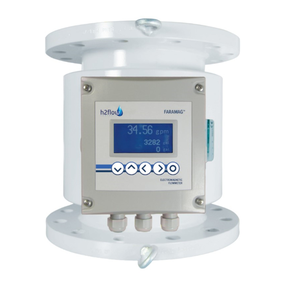
- Page 1 English Rev.1.2 6/2020 FaraMag™ mag meter FM500 MODELS IMPORTANT NOTE: For the most up-to-date version of this manual, please visit www.h2fl ow.net/product-literature Operating Manual (EN) www.h2fl ow.net • Tel: 888-635-0296 (Toll Free) (+1) 419-841-7774 (International)
-
Page 2: Table Of Contents
G-4. datalogger sub-menu ..........16 H. function of the third electrode ..............17 I. password setting ................... 17 J. GSM module activation ................18 Troubleshooting ....................18 Notes ......................... 19 Warranty ........................20 www.h2flow.net • Tel: 888-635-0296 (Toll Free) (+1) 419-841-7774 (International) -
Page 3: Description
15,216 19,813 31,700 44,380 61,023 79,251 100,649 124,425 NOTE: Please consult the factory for accurate flow range data for models smaller than 1-inch in diameter and larger than 40-inches in diameter. www.h2flow.net • Tel: 888-635-0296 (Toll Free) (+1) 419-841-7774 (International) -
Page 4: Technical Data
An optional 12/24/VAC/VDC that needs to be plugged into a standard receptacle is also available. The power supply cord should be firmly inserted into the receptacle. Contact the factory for additional information about power supply options. www.h2flow.net • Tel: 888-635-0296 (Toll Free) (+1) 419-841-7774 (International) -
Page 5: Dimensions
19.69 (500) 23.43 (595) 21 (533) 185.2 (84) 23.62 (600) 25.39 (645) 23.5 (597) 249.1 (113) 23.62 (600) 29.53 (750) 27.5 (699) 392.4 (178) PLEASE CONSULT FACTORY FOR ACCURATE WEIGHTS & DIMENSIONS www.h2flow.net • Tel: 888-635-0296 (Toll Free) (+1) 419-841-7774 (International) -
Page 6: Installation Note
5. installation note IMPORTANT If the instrument has been disconnected from it’s power supply for a period of more than 6 months, the internal clock battery may be empty. It is recommended to check the time and date when putting the instrument into operation after extensive downtime. -
Page 7: Electrical Connections
7. electrical connections CAUTION PLEASE BE AWARE THAN AN INDUCTION FLOW METER IS AN ELECTRONIC DEVICE; THE FOLLOWING STEPS SHOULD BE PERFORMED BY A QUALIFIED ELECTRICIAN! ⏚) Ensure that the fl ow sensor frame is connected to ground ( ; it is recommended that the ground terminal at the outside of the sensor is used for this purpose. - Page 8 Switch power supply on only after the sensor link cable and external device signal cables are connected! 4. Connect external devices that utilize current output or pulse outputs to terminals BIN1, BIN2, and ANAL. All outputs are isolated. www.h2flow.net • Tel: 888-635-0296 (Toll Free) (+1) 419-841-7774 (International)
-
Page 9: Instrument Start
8. instrument start When the power supply is switched on, the instrument display shows step-by-step messages POWER ON and TEST INT CL 1 to TEST INT CL 30. 2. After completing internal tests, the instrument enters to measuring mode. Basic data includes immediate fl ow rate and total volume in positive and negative fl ow directions. -
Page 10: Menu Options, Commands
Configuration of internal real-time clock PASSWORD Password setting Selection of immediate flow rate units and displayed Counter reset, check of the AD transducer function, DISPLAY SERVICE decimal places of counters information on software version www.h2flow.net • Tel: 888-635-0296 (Toll Free) (+1) 419-841-7774 (International) -
Page 11: Multi-Functional Outputs
Multi-functional outputs The fl ow meter is equipped with two multi-functional outputs. Relay or optotransistor contacts are connected to BIN1 terminals, while BIN2 terminals are used for optotransistor only. Use jumper NC-OC-NO above BIN1 terminals to set their function. a) Output works as optotransistor b) Relay contacts are normally open c) Relay contacts are normally closed Outputs can function as:... -
Page 12: B-2. Status Report Setting
The instrument will switch to display mode and work with the new parameters until it is switched off. When the instrument is switched on again, it will use the original/default parameters. www.h2flow.net • Tel: 888-635-0296 (Toll Free) (+1) 419-841-7774 (International) -
Page 13: Display
The instrument will switch to display mode and work with the new parameters until it is switched off. When the instrument is switched on again, it will use the original/default parameters. www.h2flow.net • Tel: 888-635-0296 (Toll Free) (+1) 419-841-7774 (International) -
Page 14: Dead Band Setting
Dead band setting Basic dead band of the instrument near the zero fl ow rate is 0.1 l/s. This dead band can be changed so that it would be possible to suppress undesirable fl ow rate values occurring due to liquid surges and vibrations in tubing at the zero fl ow rate. WARNING EXTENSION OF THE DEAD BAND INCREASES MEASUREMENT ERROR AT LOW FLOW RATES. -
Page 15: G-1. Datalogger Setting Without Time Mask
5. Select the option PER and confirm your selection by pressing the EXE button. Use the EDIT command to enable interval editing in minutes. Enter the interval length and use the RETURN command to return to the sub-menu. www.h2flow.net • Tel: 888-635-0296 (Toll Free) (+1) 419-841-7774 (International) -
Page 16: G-3. Examples Of Time Mask Setting
SUB-MENU OPTIONS RETURN Return to previous menu RUN* Datalogger operating STOP Datalogger stop START Datalogger start with deleting previous samples Time interval setting MASK Time mask configuration Selecting of optional values www.h2flow.net • Tel: 888-635-0296 (Toll Free) (+1) 419-841-7774 (International) -
Page 17: Function Of The Third Electrode
The instrument will switch to display mode and work with the new parameters until it is switched off. When the instrument is switched on again, it will use the original/default parameters. www.h2flow.net • Tel: 888-635-0296 (Toll Free) (+1) 419-841-7774 (International) -
Page 18: Gsm Module Activation
10. troubleshooting PROBLEM SOLUTION Sample • Solution 1 • Solution 2 Sample • Solution Sample • Solution 1 • • • • • www.h2flow.net • Tel: 888-635-0296 (Toll Free) (+1) 419-841-7774 (International) -
Page 19: Notes
PROBLEM SOLUTION Sample • Solution 1 • Solution 2 Sample • Solution Sample • Solution 1 • • • • • 11. notes www.h2flow.net • Tel: 888-635-0296 (Toll Free) (+1) 419-841-7774 (International) -
Page 20: Warranty
Failure to present this evidence may limit H2fl ow Controls Inc’s obligations under this warranty. THIS WARRANTY IS GIVEN BY H2FLOW CONTROLS INC. IN LIEU OF ANY OTHER WARRANTIES, EXPRESSED OR IMPLIED, INCLUDING BUT NOT LIMITED TO ANY IMPLIED WARRANTY OF MERCHANTABILITY, NON INFRINGEMENT OR FITNESS FOR A PARTICULAR PURPOSE.
Need help?
Do you have a question about the FaraMag FM500 and is the answer not in the manual?
Questions and answers