
Related Manuals for GEA HGX4 CO2 Series


Summary of Contents for GEA HGX4 CO2 Series
- Page 1 Bock Compressor HGX4 CO Assembly instructions HGX4/310-4 CO HGX4/385-4 CO HGX4/465-4 CO HGX4/555-4 CO engineering for a better world GEA Refrigeration Technologies...
- Page 2 Observe the safety instructions contained in these instructions. These instructions must be passed onto the end customer along with the unit in which the compres- sor is installed. Manufacturer GEA Bock GmbH 72636 Frickenhausen Contact GEA Bock GmbH Benzstraße 7...
-
Page 3: Table Of Contents
Contents Page Safety 1.1 Identification of safety instructions 1.2 Qualifications required of personnel 1.3 General safety instructions 1.4 Intended use Product description 2.1 Short description 2.2 Name plate 2.3 Type key Areas of application 3.1 Refrigerants 3.2 Oil charge 3.3 Limits of application Compressor assembly 4.1 Setting up 4.2 Pipe connections 4.3 Pipes 4.4 Laying suction and pressure lines... -
Page 4: Safety
1| Safety 1.1 Identification of safety instructions: Indicates a dangerous situation which, if not DANGER! avoided, will cause immediate fatal or serious injury. Indicates a dangerous situation which, if not WARNING! avoided, may cause fatal or serious injury. Indicates a dangerous situation which, if not CAUTION! avoided, may cause fairly severe or minor injury. Indicates a situation which, if not ATTENTION! avoided, may cause property damage. INFO! Important information or tips on simplifying work. 1.2 Qualifications required of personnel WARNING! I nadequately qualified personnel poses the risk of accidents, the consequence being serious or fatal injury. Work on compressors must therefore only be performed by personnel with the qualifica- tions listed below: • F or example, a refrigeration technician, refrigeration mechatron-... -
Page 5: Intended Use
1| Safety 1.4 Intended use These assembly instructions describe the standard version of the HGX4 -CO manufactured by Bock. The compressor is intended for use with CO in sub-critical systems in compliance with the limits of application. Only the refrigerant specified in these instructions may be used. Any other use of the compressor is prohibited! WARNING! The compressor may not be used in potentially explosive environments! The Bock refrigerating compressor named in the title is intended for installing in a machine (within... -
Page 6: Product Description
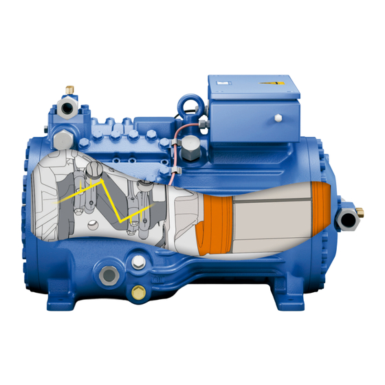
2| Product description 2.1 Short description • Semi-hermetic four-cylinder reciprocating compressor with suction-gas cooled drive motor. • Flange-mounted drive motor on the compressor case. • The stream of refrigerant sucked out of the evaporator flows over the motor and cools it intensively. In this way, the motor can be kept at a relatively low temperature level, particularly under high loads Transport eyelet Valve plate... -
Page 7: Type Key
2| Product description 2.2 Name plate (example) GEA Bock GmbH 72636 Frickenhausen, Germany AS12345-001 C85E 27/55 Fig. 3 Type designation Voltage, circuit, frequency 50 Hz Machine number Nominal rotation speed maximum operating current Displacement Starting current (rotor blocked) Voltage, circuit, frequency 60 Hz Y: Part winding 1 10 Nominal rotation speed... -
Page 8: Areas Of Application
3| Areas of application 3.1 Refrigerants • CO R744 3.2 Oil charge The compressors are filled at the factory with the following oil type: Bock C 85 E (only this oil may be used) ATTENTION! The oil level must be in the visible part of the sight glass; damage max. oil level to the compressor is possible if min. oil level overfilled or underfilled! Fig. -
Page 9: Compressor Assembly
4| Compressor assembly INFO! New compressors are factory-filled with inert gas (3 bar nitrogen). Leave this service charge in the compressor for as long as possible and prevent the ingress of air. Check the compressor for transport damage before starting any work. 4.1 Setting up Use transport eyelet. Do not lift manually! Use lifting gear! Fig. -
Page 10: Pipes
4| Compressor assembly 4.3 Pipes Pipes and system components must be clean and dry inside and free of scale, swarf and layers of rust and phosphate. Only use air-tight parts. Lay pipes correctly. Suitable vibration compensators must be provided to prevent pipes being cracked and broken by severe vibrations. -
Page 11: Operating The Shut-Off Valves
4| Compressor assembly 4.5 Operating the shut-off valves Before opening or closing the shut-off valve, release the valve spindle seal by approx. ¼ of a turn counter-clockwise. After activating the shut-off valve, re-tighten the adjustable valve spindle seal clockwise. Release Tighten Valve spindle seal Fig. -
Page 12: Information For Contactor And Motor Contactor Selection Dgb
5| Electrical connection Electrical connection DANGER! H igh voltage! Risk of electric shock! Only carry out work when the electrical system is disconnected from the power supply! INFO! Connect the compressor motor in accordance with the circuit diagram (see inside of terminal box). Use suitable cable entry point of the correct protection type (see name plate) for routing cables into the terminal box. -
Page 13: Standard Motor, Design For Direct Or Partial Winding Start
5| Electrical connection 5.2 Standard motor, design for direct or partial winding start Designation on the name plate Sticker on the terminal box Y/YY Compressors with this marking are suitable for direct or partial winding start. The motor winding is subdivided into two parts: Partial winding 1 = 66% and part winding 2 = 33%. This winding division reduces the start-up current needed for a part winding start to approx. -
Page 14: Basic Circuit Diagram For Partial Winding Start With Standard Motor F
5.3 Basic circuit diagram for partial winding start with standard motor ... - Page 15 ...
-
Page 16: Electronic Trigger Unit Mp
5| Electrical connection 5.4 Electronic trigger unit MP 10 The compressor motor is fitted with cold conductor temperature sensors (PTC) connected to the electronic trigger unit MP 10 in the terminal box. Readiness to operate is signalled by the H3 LED (green) after the power supply is applied. -
Page 17: Oil Sump Heater (Accessories)
5| Electrical connection 5.6 Function test of the trigger unit MP 10 Before start-up, troubleshooting or making changes to the control power circuit, check the functionality of the trigger unit: LED H1 LED H2 LED H3 Procedure green • Interrupt power supply (L1 or S1) •... -
Page 18: Commissioning
6| Commissioning 6.1 Preparations for start-up INFO! In order to protect the compressor against inadmissible operating conditions, high-pressure and low-pressure pressostats controls are mandatory on the installation side. The compressor has undergone trials in the factory and all functions have been tested. There are therefore no special running-in instructions. -
Page 19: Evacuation
6| Commissioning 6.4 Evacuation ATTENTION! Do not start the compressor if it is under vacuum. Do not apply any voltage - even for test purposes (must only be operated with refrigerant). Under vacuum, the spark-over and creepage current distances of the terminal board connection bolts shorten;... -
Page 20: Start-Up
6| Commissioning 6.6 Start-up WARNING! Ensure that both shut-off valves are open before starting the compressor! Check that the safety and protection devices (pressure switch, motor protection, electrical contact protection measures, etc.) are functioning properly. Switch on the compressor and let it run for at least 10 minutes. The machine should reach a state of equilibrium. -
Page 21: Connection Of Oil Level Regulator
6| Commissioning 6.8 Avoid slugging ATTENTION! Slugging can result in damage to the compressor and cause refrigerant to leak. To prevent slugging: The complete refrigeration plant must be properly designed. All components must be compatibly rated with each other with regard to output (particularly the evaporator and expansion valves). -
Page 22: Maintenance
7| Maintenance 7.1 Preparation WARNING! Before starting any work on the compressor: Switch off the compressor and secure it to prevent a restart. Relieve compressor of system pressure. Prevent air from infiltrating the system! After maintenance has been performed: Connect safety switch. Evacuate compressor. Release switch-on lock. 7.2 Work to be carried out In order to guarantee optimum operational reliability and service life of the compressor, we recommend carrying out servicing and inspection work at regular intervals: Oil change: not mandatory for factory-produced series systems. -
Page 23: Spare Parts Recommendation
7| Maintenance 7.3 Spare parts recommendation HGX4 / ... 310-4 CO 385-4 CO 465-4 CO 555-4 CO Designation Item No. Item No. Item No. Item No. Set of gaskets 80472 08913 Valve plate kit 80473 80438 80438 80439 Set piston/connecting rod 80399 80399 80433... -
Page 24: Decommissioning
7| Maintenance 7.6 Decommissioning Close the shut-off valves on the compressor. CO does not need to be recycled and can therefore be blown off into the environment. It is essential to ensure good ventilation or conduct the CO into the outdoors to avoid danger of suffocation. When releasing CO2, avoid a fast drop in pressure to prevent oil from exiting with it. -
Page 25: Technical Data
8| Technical data 380-420 V Y/YY - 3 - 50 Hz PW 440-480 V Y/YY - 3 - 60 Hz PW... -
Page 26: Dimensions And Connections
9| Dimensions and connections ca.360 DV L1 Centre of gravity ca.235 ÖV ca.360 Schwingungsdämpfer ca.690 ca.360 Vibration absorbers DV L1 Amortisseurs de vibration DV L1 Maße Zubehör / Dimensions Accessories / Dimensions Acc ca.360 ca.360 Anschlüsse Saugabsperrventil, Rohr (L)* DV L1 Druckabsperrventil, Rohr (L)* Anschluß... - Page 27 9| Dimensions and connections Suction line see technical data, Chapter 8 Discharge line Connection suction side, not lockable 8 “ NPTF Connection suction side, lockable 16 “ UNF Connection discharge side, not lockable 8 “ NPTF Connection discharge side, lockable 16 “...
-
Page 28: Declaration Of Conformity And Installation
DECLARATION OF INSTALLATION for using the compressors within the European Union (in accordance with Machinery Directive 2006/42/EC) The manufacturer: GEA Bock GmbH, Benzstraße 7 72636 Frickenhausen, Tel.: 07022/9454-0 hereby declares that the refrigerating compressor HGX4 -CO complies with the basic require- ments of Appendix II 1B of the Machinery Directive 2006/42/EC. -
Page 29: Service
Dear customer, Bock compressors are top-quality, reliable and service-friendly quality products. If you have any questions about installation, operation and accessories, please contact our technical service or specialist wholesaler and/or our representative. The Bock service team can be contacted by phone with a toll-free hotline 00 800 / 800 000 88 or via e-mail: bock@gea.com. Yours faithfully GEA Bock GmbH Benzstraße 7 Sehr geehrter unde, 72636 Frickenhausen Bock- erdichter sind hochwertige, u verl ssige und se rvicefreundliche ualit tsprodu kte. - Page 30 • • GEA Group is a global engineering company with multi-billion euro sales and operations in more than 50 countries. Founded in 1881, the company is one of the largest providers of innovative equipment and process technology. GEA Group is listed in the STOXX® Europe 600 index.
Need help?
Do you have a question about the HGX4 CO2 Series and is the answer not in the manual?
Questions and answers