Table of Contents
Advertisement
Quick Links
Advertisement
Table of Contents

Related Manuals for GEA HG22P Series


Summary of Contents for GEA HG22P Series
- Page 1 GEA Bock Compressor HG22P Assembly instructions HG22P/125-4 HG22P/125-4 S HGX22P/125-4 HGX22P/125-4 S HG22P/160-4 HG22P/160-4 S HGX22P/160-4 HGX22P/160-4 S HG22P/190-4 HG22P/190-4 S HGX22P/190-4 HGX22P/190-4 S engineering for a better world...
-
Page 2: Table Of Contents
Observe the safety instructions contained in these instructions. These instructions must be passed onto the end customer along with the unit in which the compres- sor is installed. Manufacturer GEA Bock GmbH 72636 Frickenhausen Contact GEA Bock GmbH Benzstraße 7... - Page 3 Contents Page Areas of application 3.1 Refrigerants 3.2 Oil charge 3.3 Limits of application Compressor assembly 4.1 Storage and transport 4.2 Setting up 4.3 Pipe connections 4.4 Pipes 4.5 Laying suction and pressure lines 4.6 Operating the shut-off valves 4.7 Operating mode of the lockable service connections Electrical connection 5.1 Information for contactor and motor contactor selection 5.2 Connection of the driving motor...
-
Page 4: Safety
1| Safety 1.1 Identification of safety instructions: Indicates a dangerous situation which, if not DANGER! avoided, will cause immediate fatal or serious injury. Indicates a dangerous situation which, if not WARNING! avoided, may cause fatal or serious injury. Indicates a dangerous situation which, if not CAUTION! avoided, may cause fairly severe or minor injury. Indicates a situation which, if not ATTENTION! avoided, may cause property damage. INFO! Important information or tips on simplifying work. 1.2 Qualifications required of personnel WARNING! I nadequately qualified personnel poses the risk of accidents, the consequence being serious or fatal injury. Work on compressors must therefore only be performed by personnel with the qualifica- tions listed below: •... -
Page 5: Intended Use
WARNING! The compressor may not be used in potentially explosive environments! The GEA Bock refrigerating compressor named in the title is intended for installing in a machine (within the EU according to the EU Directives 2006/42/EC Machinery Directive, 97/23/EC Pressure Equipment Directive and 2006/95/EC – Low Voltage Directive). -
Page 6: Product Description
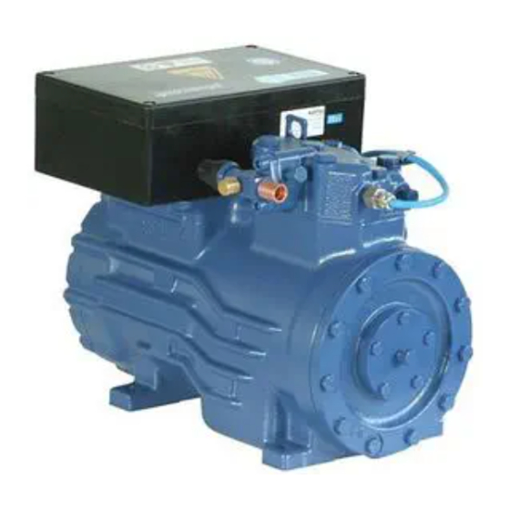
2| Product description 2.1 Short description • Semi-hermetic two-cylinder reciprocating compressor with oil pump lubrication. • Suction gas cooled drive motor. Transport eyelet Valve plate Name plate Oil pump Oil sight glass Fig. 1 Cylinder cover Terminal box Discharge shut-off valve Drive section Suction Motor section... -
Page 7: Type Key
2| Product description Typschild (Beispiel) 2.2 Name plate (example) GEA Bock GmbH 72636 Frickenhausen, Germany HGX22P/190-4 AS35830A001 SE 55 Fig. 3 Typbezeichnung Spannung, Schaltung, Frequenz 50 Hz Type designation Voltage, circuit, frequency Maschinennummer Nenndrehzahl 50 Hz Machine number Nominal rotation speed maximaler Betriebsstrom... -
Page 8: Areas Of Application
3| Areas of application 3.1 Refrigerants • HFKW / HFC: R134a, R404A/R507, R407C • (H)FCKW / (H)CFC: 3.2 Oil charge The compressors are filled at the factory with the following oil type: - for R134a, R404A/R507, R407C FUCHS Reniso Triton SE 55 - for R22 FUCHS Reniso SP 46 Compressors with ester oil charge (FUCHS Reniso Triton SE 55) are marked with an X in the type designation (e.g. HGX22P/190-4). INFO! For refilling, we recommend the above oil types. Alternatives: see lubricants table, Chapter 7.5. - Page 9 R134a Fig. 5 R407C Fig. 6 Unlimited application range Supplementary cooling or reduced suction gas temperature Supplementary cooling and R404A/R507 reduced suction gas temperature Motor version S (more powerful motor) Evaporation temperature (°C) Condensing temperature (°C) Fig. 7 Suction gas superheat (K) Suction gas temperature (°C) Max. permissible operating pressure (LP/HP) : 19/28 bar LP = Low pressure HP = High pressure Design for other...
-
Page 10: Compressor Assembly
4| Compressor assembly INFO! New compressors are factory-filled with inert gas (3 bar nitrogen). Leave this service charge in the compressor for as long as possible and prevent the ingress of air. Check the compressor for transport damage before starting any work. 4.1 Storage and transport Storage at (-30°C) - (+70°C), maximum permissible relative humidity 10% - 95%, no condensation Do not store in a corrosive, dusty, vaporous atmosphere or in a com- bustible environment. -
Page 11: Pipes
4| Compressor assembly The pipe connections have graduated inside diameters so that pipes with standart millimetre and inch dimensions can be used. The connection diameters of the shut-off valves are rated for maximum compressor output. The actual required pipe cross section must be matched to the output. The same applies for non-return valves. Fig. 14: graduated internal diameter 4.4 Pipes... -
Page 12: Operating The Shut-Off Valves
4| Compressor assembly 4.6 Operating the shut-off valves Before opening or closing the shut-off valve, release the valve spindle seal by approx. ¼ of a turn counter-clockwise. After activating the shut-off valve, re-tighten the adjustable valve spindle seal clockwise. Tighten Release Valve spindle seal Fig. -
Page 13: Electrical Connection
5| Electrical connection Electrical connection DANGER Risk of electric shock! High voltage! Only carry out work when the electrical system is disconnected from the power supply! INFO Connect the compressor motor in accordance with the circuit diagram (see inside of terminal box). Use suitable cable entry point of the correct protection type (see name plate) for routing cables into the terminal box. Insert the strain reliefs and prevent chafe marks on the cables. Compare the voltage and frequency values with the data for the mains power supply. - Page 14 5.3 Circuit diagramm for direct start 230 V ∆ / 400 V Y --> compressor with MP10 I> I> I> X1 L1 L1 N N 43 43 11 -EC1 Θ MP10 X2 1 Compressor terminal box Klemmenkasten Verdichter Fig. 20 Cold conductor (PTC sensor) motor winding Thermal protection thermostat (PTC sensor) Load circuit safety switches...
- Page 15 L1.1 L2.1 L3.1 L1.2 A1 Alarm Motorschutz Alarm motor protection Overheating BT1, BT2 A2 Übertemperatur BT1, BT2 P< Alarm high pressure A3 Alarm Hochdruck Main switch Control voltage switch Compressor motor Compressor contactor MP10 Electronic trigger unit MP10 Oil sump heater...
-
Page 16: Electronic Trigger Unit Mp10
5| Electrical connection 5.4 Electronic trigger unit MP 10 The compressor motor is fitted with cold conductor temperature sensors (PTC) connected to the electronic trigger unit MP 10 in the terminal box. Readiness to operate is signalled by the H3 LED (green) after the power supply is applied. In the case of excess temperature in the motor winding, the unit switches off the compressor and the H1 LED lights red. - Page 17 5| Electrical connection 5.6 Function test of the trigger unit MP 10 Before start-up, troubleshooting or making changes to the control power circuit, check the functionality of the trigger unit: LED H1 LED H2 LED H3 Procedure green • Interrupt power supply (L1 or SF1) •...
- Page 18 5.7 Circuit diagramm for direct start 230 V ∆ / 400 V Y --> compressor with INT69 G I> I> I> B1 B2 -EC1 INT69 G Θ Compressor terminal box Klemmenkasten Verdichter Fig. 22 Cold conductor (PTC sensor) motor winding Thermal protection thermostat (PTC sensor) Load circuit safety switches Control power circuit fuse Safety chain (high/low pressure monitoring) Release switch (thermostat/pressostat)
- Page 19 L1.1 Alarm motor protection A1 Alarm Motorschutz Overheating BT1, BT2 A2 Übertemperatur BT1, BT2 P< Alarm high pressure A3 Alarm Hochdruck Main switch Control voltage switch Compressor motor Compressor contactor INT69 G Electronic trigger unit INT69 G Oil sump heater...
-
Page 20: Electronic Trigger Unit Int69 G
5| Electrical connection 5.8 Electronic trigger unit INT69 G The compressor motor is fitted with cold conductor temperature sensors (PTC) connected to the electronic trigger unit INT69 G in the terminal box. In case of excess temperature in the motor winding, the INT69 G deactivates the motor contactor. -
Page 21: Start Unloader
INT69 G switch-on 11-14 B2 12 14 11 Remove PTC connector 11-12 Fig. 24 Insert PTC connector 11-12 Reset after mains on 11-14 5.11 Start unloader To avoid current peaks during the starting phase we recommend using the GEA Bock-ESS soft starting device (Electronic Soft Start). Refer to "Accessories" for further information. -
Page 22: Preparations For Start-Up
6| Commissioning 6.1 Preparations for start-up INFO! In order to protect the compressor against inadmissible operating conditions, high-pressure and low-pressure pressostats controls are mandatory on the installation side. The compressor has undergone trials in the factory and all functions have been tested. There are therefore no special running-in instructions. Check the compressor for transport damage! 6.2 Pressure strength test DANGER! -
Page 23: Refrigerant Charge
6| Commissioning 6.5 Refrigerant charge CAUTION! Wear personal protective clothing such as goggles and protective gloves! Make sure that the suction and pressure line shut-off valves are open. With the compressor switched off, add the liquid refrigerant directly to the condenser or receiver, breaking the vacuum. If the refrigerant needs topping up after starting the compressor, it can be topped up in vapour form on the suction side, or, taking suitable precautions, also in liquid form at the inlet to the evaporator. -
Page 24: Connection Of Oil Level Regulator
7.3 Spare parts recommendation HG22P / ... 125-4 (S) 160-4 (S) 190-4 (S) Designation Ref. No. Ref. No. Ref. No. Set of gaskets 80313 Valve plate kit 80305 80306 Oil pump kit 08324 Only use genuine GEA Bock spare parts! -
Page 25: Accessories
7| Maintenance 7.4 Accessories Available accessories can be found on the Internet at www.gea.com 7.5 Extract from the lubricants table The oil type filled as standard in the factory is marked on the name plate . This oil type should be used as a preference. Alternatives are stated in the extract from our lubricants table below. -
Page 26: Technical Data
8| Technical data 220-240 V ∆ / 380-420 V Y - 3 - 50 Hz 265-290 V ∆ / 440-480 V Y - 3 - 60 Hz... -
Page 27: Dimensions And Connections
9| Dimensions and connections Maß Maße Zubehör / D Centre of gravity H,D1 H,D1 ca.115 ca.115 ca.240 ca.5 ca.470 Schwingungsdämpfer ca.240 Vibration absorbers ca.470 Amortisseurs de vibration Massenschwerp Schwingungsdämpfer ca.115 Centre of gravity Vibration absorbers Centre de gravit Amortisseurs de vibration Massenschwerpunkt Centre of gravity Centre de gravité... -
Page 28: Declaration Of Conformity And Installation
Applied harmonised standard: EN 60034-1:2010 EN 60204-1:2006 DECLARATION OF INSTALLATION for using the compressors within the European Union (in accordance with Machinery Directive 2006/42/EC) The manufacturer: GEA Bock GmbH, Benzstraße 7 72636 Frickenhausen, Tel.: 07022/9454-0 hereby declares that the refrigerating compressor HG22P complies with the basic requirements of Appendix II 1B of the Machinery Directive 2006/42/EC. Applied harmonised standard: EN 12693:2008 and the corresponding standards referenced A partly completed machine may only be put into operation when it has been established that the machine, into which the partly completed machine is to be installed, conforms to the r egulations of the Machinery Directive (2006/42/EC). -
Page 29: Service
11| Service Dear customer, GEA Bock compressors are top-quality, reliable and service-friendly quality products. If you have any questions about installation, operation and accessories, please contact our techni- cal service or specialist wholesaler and/or our representative. The GEA Bock service team can be contacted by phone with a toll-free hotline 00 800 / 800 000 88 or via e-mail: refrigeration@gea.com Yours faithfully GEA Bock GmbH Benzstraße 7... - Page 30 • • GEA Group is a global engineering company with multi-billion euro sales and operations in more than 50 countries. Founded in 1881, the company is one of the largest providers of innovative equipment and process technology. GEA Group is listed in the STOXX Europe 600 index.
Need help?
Do you have a question about the HG22P Series and is the answer not in the manual?
Questions and answers