
Subscribe to Our Youtube Channel
Related Manuals for Intel Atom N2800


Summary of Contents for Intel Atom N2800
- Page 1 Embedded Intel® Atom™ Processor N2800 with Intel® NM10 Express Chipset Development Kit User’s Manual February 2012 Document Number: 326570...
- Page 2 INFRINGEMENT OF ANY PATENT, COPYRIGHT OR OTHER INTELLECTUAL PROPERTY RIGHT. A "Mission Critical Application" is any application in which failure of the Intel Product could result, directly or indirectly, in personal injury or death. SHOULD YOU PURCHASE OR USE INTEL'S PRODUCTS FOR ANY...
- Page 3 SLGXX Ordering Information The name of this Development Kit is the Intel® Atom™ Processor N2800 with Intel® NM10 Express Chipset Development Kit. This document is the user guide for this Kit. For ordering purposes, the Part Number of this Kit is EMBCDTNMMTDVK and the Kit‘s product code is MM# 920354.
- Page 4 Embedded Intel® Atom™ Processor N2800 with Intel® NM10 Express Chipset Development Kit User‘s Manual Preface This User‘s Manual describes the typical hardware set-up procedures, features, and use of the evaluation board and other components included in the Intel® Atom™ Processor N2800 with Intel® NM10 Express Development Kit. The Intel Embedded ®...
- Page 5 Embedded Intel® Atom™ Processor N2800 with Intel® NM10 Express Chipset Development Kit User‘s Manual Other Common Notation Used after a signal name to identify an active-low signal (such as USBP0#) Gigabyte (1,073,741,824 bytes) GB/s Gigabytes per second Gb/s Gigabits per second...
-
Page 6: Table Of Contents
Embedded Intel® Atom™ Processor N2800 with Intel® NM10 Express Chipset Development Kit User‘s Manual Contents 1 Development Kit Contents ........... 12 1.1 Included Hardware and Documentation ..........12 1.2 Development Kit Preview ..............13 ® 2 Intel Embedded Board N2800 Overview ......14 2.1 Overview .................. - Page 7 Embedded Intel® Atom™ Processor N2800 with Intel® NM10 Express Chipset Development Kit User‘s Manual 2.15.1 ACPI ................44 2.15.2 Hardware Support ..............46 2.16 Debug Interfaces ................49 3 Technical Reference ............50 3.1 Memory Resources ................50 3.1.1 Addressable Memory ............. 50 3.1.2...
- Page 8 Embedded Intel® Atom™ Processor N2800 with Intel® NM10 Express Chipset Development Kit User‘s Manual 5 Error Messages and Beep Codes .......... 92 5.1 Speaker ..................92 5.2 BIOS Beep Codes ................92 5.3 Front-panel Power LED Blink Codes ............. 93 5.4 BIOS Error Messages ................
- Page 9 Embedded Intel® Atom™ Processor N2800 with Intel® NM10 Express Chipset Development Kit User‘s Manual Figures Figure 1. Major Board Components (Top) ........... 16 Figure 2. Major Board Components (Bottom) ..........18 Figure 3. Block Diagram of Development Kit ..........19 Figure 4.
- Page 10 Embedded Intel® Atom™ Processor N2800 with Intel® NM10 Express Chipset Development Kit User‘s Manual Tables Table 1. Feature Summary ............... 14 Table 2. Components Shown in Figure 1 ............ 17 Table 3. Components Shown in Figure 2 ............ 18 Table 4. Maximum Resolutions Supported by the Intel® Atom™ Processor N2800 with Intel®...
- Page 11 Embedded Intel® Atom™ Processor N2800 with Intel® NM10 Express Chipset Development Kit User‘s Manual Table 44. Boot Device Menu Options ............89 Table 45. Master Key and User Hard Drive Password Functions ..... 90 Table 46. Supervisor and User Password Functions ........91 Table 47.
-
Page 12: Development Kit Contents
Embedded Intel® Atom™ Processor N2800 with Intel® NM10 Express Chipset Development Kit User‘s Manual Development Kit Contents Included Hardware and Documentation Each development kit ships as a complete system in a mini-ITX chassis (Size: 192 x 210 x 62mm.) ... -
Page 13: Development Kit Preview
Embedded Intel® Atom™ Processor N2800 with Intel® NM10 Express Chipset Development Kit User‘s Manual Development Kit Preview 1.2.1.1 Front 1.2.1.2 Inside 1.2.1.3 Back... -
Page 14: Intel Embedded Board N2800 Overview
Embedded Intel® Atom™ Processor N2800 with Intel® NM10 Express Chipset Development Kit User‘s Manual ® Intel Embedded Board N2800 Overview Overview 2.1.1 Feature Summary Table 1 summarizes the major features of the development kit. Table 1. Feature Summary Mini-ITX (6.7 inches by 6.7 inches [170.18 millimeters by 170.18 millimeters]) - Page 15 Embedded Intel® Atom™ Processor N2800 with Intel® NM10 Express Chipset Development Kit User‘s Manual Table 1. Feature Summary (continued) Legacy I/O Control Nuvoton* Legacy I/O Controller (Nuvoton* W83677DHG) that provides: • Hardware management support • Multiple serial ports via onboard headers •...
-
Page 16: Embedded Board Layout (Top)
Embedded Intel® Atom™ Processor N2800 with Intel® NM10 Express Chipset Development Kit User‘s Manual 2.1.2 Embedded Board Layout (Top) Figure 1 shows the location of the major components on the top-side of the Intel N2800 Embedded Board. Figure 1. Major Board Components (Top) -
Page 17: Table 2. Components Shown In Figure 1
Embedded Intel® Atom™ Processor N2800 with Intel® NM10 Express Chipset Development Kit User‘s Manual Table 2 lists the components identified in Figure 1. Table 2. Components Shown in Figure 1 Item/callout from Figure 1 Description Debug connector Battery Back panel connectors (refer to Section 3.2.1) -
Page 18: Embedded Board Layout (Bottom)
Embedded Intel® Atom™ Processor N2800 with Intel® NM10 Express Chipset Development Kit User‘s Manual 2.1.3 Embedded Board Layout (Bottom) Figure 2 shows the location of the major components on the bottom-side of the Intel Embedded Board N2800. Figure 2. Major Board Components (Bottom) Table 3. -
Page 19: Block Diagram
Embedded Intel® Atom™ Processor N2800 with Intel® NM10 Express Chipset Development Kit User‘s Manual 2.1.4 Block Diagram Figure 3 is a block diagram of the major functional areas of the Intel® Embedded Board N2800. Figure 3. Block Diagram of Development Kit... -
Page 20: Online Support
Embedded Intel® Atom™ Processor N2800 with Intel® NM10 Express Chipset Development Kit User‘s Manual Online Support For information about… Visit this web site: ® http://www.intel.com/p/en_US/embedded/hwsw/hardware/atom Intel Atom Processor N2800 and -n2000-d2000/overview NM10 Express Chipset Platform Overview Chipset information http://www.intel.com/products/desktop/chipsets/index.htm (Search for NM10 Express Chipset) BIOS and driver updates http://downloadcenter.intel.com... -
Page 21: Bios Vendors
Embedded Intel® Atom™ Processor N2800 with Intel® NM10 Express Chipset Development Kit User‘s Manual BIOS vendors The BIOS vendors are: BIOS vendors American Megatrends* Insyde Software* Phoenix Technologies Byosoft* Intel strives to provide customers with a complete development environment supporting customer applications and operating systems. Any software provided in development kits is subject to change without notice. -
Page 22: Intel ® Embedded Board N2800 Graphics Subsystem
Embedded Intel® Atom™ Processor N2800 with Intel® NM10 Express Chipset Development Kit User‘s Manual ® 2.5.1 Intel Embedded Board N2800 Graphics Subsystem ® 2.5.1.1 Intel Graphics Media Accelerator 3600 Graphics ® Controller (Intel GMA) The Intel® Atom™ Processor N2800 contains an integrated graphics core, the Intel®... -
Page 23: Table 4. Maximum Resolutions Supported By The Intel® Atom™ Processor N2800
Embedded Intel® Atom™ Processor N2800 with Intel® NM10 Express Chipset Development Kit User‘s Manual Table 4. Maximum Resolutions Supported by the Intel® Atom™ Processor N2800 with Intel® NM10 Express Chipset Graphic interfaces Interfaces Max resolution Remark LVDS (Dual channel) 1366 x 768 60 Hz;... -
Page 24: System Memory
Embedded Intel® Atom™ Processor N2800 with Intel® NM10 Express Chipset Development Kit User‘s Manual System Memory The board has two 204-pin SO-DIMM sockets and supports the following memory features: 1.5V DDR3-800 and DDR3-1066 SO-DIMMs with gold-plated contacts Unbuffered, non-ECC, Raw Card B (1Rx8) and Raw Card-F (2Rx8) SO-DIMMs only ... -
Page 25: Table 5. Supported Memory Configurations
Embedded Intel® Atom™ Processor N2800 with Intel® NM10 Express Chipset Development Kit User‘s Manual Table 5 lists the supported SO-DIMM configurations. Table 5. Supported Memory Configurations Raw Card SO-DIMM DRAM Device DRAM # of DRAM Version Capacity Technology Organization Devices... -
Page 26: Figure 4. So-Dimm Configuration
Embedded Intel® Atom™ Processor N2800 with Intel® NM10 Express Chipset Development Kit User‘s Manual Figure 4 illustrates the SO-DIMM locations. Figure 4. SO-DIMM Configuration... -
Page 27: Intel ® Nm10 Express Chipset
Embedded Intel® Atom™ Processor N2800 with Intel® NM10 Express Chipset Development Kit User‘s Manual ® Intel NM10 Express Chipset The Intel® NM10 Express Chipset with Direct Media Interface (DMI) interconnect provides interfaces to the processor and the USB, SATA, LPC, LAN, and PCI Express interfaces. -
Page 28: Table 6. Hdmi Port Status Conditions
Embedded Intel® Atom™ Processor N2800 with Intel® NM10 Express Chipset Development Kit User‘s Manual 2.8.1.2 High Definition Multimedia Interface* (HDMI*) The HDMI port supports standard, enhanced, or high definition video, plus multi- channel digital audio on a single cable. It is compatible with all ATSC and DVB HDTV standards and supports eight full range channels at 24-bit/96 kHz audio. -
Page 29: Flat Panel Display Interfaces
Embedded Intel® Atom™ Processor N2800 with Intel® NM10 Express Chipset Development Kit User‘s Manual 2.8.2 Flat Panel Display Interfaces The Kit supports flat panel display via the LVDS and Embedded DisplayPort interfaces. Figure 5 shows the flat panel connectors. Item... - Page 30 Embedded Intel® Atom™ Processor N2800 with Intel® NM10 Express Chipset Development Kit User‘s Manual 2.8.2.1 LVDS Interface The LVDS flat panel display interface supports the following: 1366 x 768 @ 60 Hz resolution Single-channel and dual-channel interface, up to 135 MHz clock rate 18 bpp and 24 bpp (VESA* and JEIDA mappings) color depth support ...
- Page 31 Embedded Intel® Atom™ Processor N2800 with Intel® NM10 Express Chipset Development Kit User‘s Manual NOTE Backlight inverter voltage option “Vin” refers to board input voltage as provided to board power input connector. 2.8.2.3 Configuration Modes Video mode configuration for eDP/LVDS displays is supported as follows: ...
- Page 32 Embedded Intel® Atom™ Processor N2800 with Intel® NM10 Express Chipset Development Kit User‘s Manual NOTE Support for flat panel display configuration complies with the following: 1. Internal flat panel display connectivity is disabled (and all parameters hidden) by default.
-
Page 33: Usb
Embedded Intel® Atom™ Processor N2800 with Intel® NM10 Express Chipset Development Kit User‘s Manual 2.8.3 The Kit supports up to ten USB ports. The port arrangement is as follows: ® Four front panel ports (via two internal headers; one header supports an Intel Z-U130 USB Solid-State Drive (or compatible SSD)) ... -
Page 34: Sata Interfaces
Embedded Intel® Atom™ Processor N2800 with Intel® NM10 Express Chipset Development Kit User‘s Manual SATA Interfaces The Kit provides two SATA ports through the Intel® NM10 Express Chipset PCH (Platform Controller Hub), which supports one device per port: One internal SATA connector (black) ... -
Page 35: 2.10 Real-Time Clock Subsystem
Embedded Intel® Atom™ Processor N2800 with Intel® NM10 Express Chipset Development Kit User‘s Manual 2.10 Real-Time Clock Subsystem A coin-cell battery (CR2032) powers the real-time clock and CMOS memory. When the computer is not plugged into a wall socket, the battery has an estimated life of three years. -
Page 36: Parallel Port
Embedded Intel® Atom™ Processor N2800 with Intel® NM10 Express Chipset Development Kit User‘s Manual 2.11.2 Parallel Port The parallel port is implemented as a 26-pin header on the board. Use the BIOS Setup program to set the parallel port mode. -
Page 37: 2.12 Audio Subsystem
Embedded Intel® Atom™ Processor N2800 with Intel® NM10 Express Chipset Development Kit User‘s Manual 2.12 Audio Subsystem The board supports Intel High Definition Audio (Intel HD Audio) subsystem via the ® ® Realtek ALC888S audio codec and the HDMI interface. The audio subsystem supports the following features: ... -
Page 38: Audio Subsystem Software
Two ports for analog line-in and analog line-out on the back panel Front panel audio header that supports Intel HD audio and AC‘97 audio (a 2 x 5-pin header that provides microphone in and headphones signals for front panel audio connectors) ... -
Page 39: Figure 7. Internal Audio Headers
Embedded Intel® Atom™ Processor N2800 with Intel® NM10 Express Chipset Development Kit User‘s Manual Figure 7 shows the location of the internal audio headers. Item Description Front panel audio header DMIC header S/PDIF header Internal stereo speakers connector Figure 7. Internal Audio Headers... -
Page 40: 2.13 Lan Subsystem
Embedded Intel® Atom™ Processor N2800 with Intel® NM10 Express Chipset Development Kit User‘s Manual 2.13 LAN Subsystem The LAN subsystem consists of the following: Intel 82574L Gigabit Ethernet Controller (10/100/1000 Mbits/s) Intel NM10 Express Chipset RJ-45 LAN connector with integrated status LEDs Additional features of the LAN subsystem include: ... -
Page 41: Lan Subsystem Software & Drivers
Embedded Intel® Atom™ Processor N2800 with Intel® NM10 Express Chipset Development Kit User‘s Manual 2.13.2 LAN Subsystem Software & Drivers LAN software and drivers are available from Intel‘s web site. For information about Refer to Obtaining LAN software and drivers http://downloadcenter.intel.com... -
Page 42: 2.14 Hardware Management Subsystem
Embedded Intel® Atom™ Processor N2800 with Intel® NM10 Express Chipset Development Kit User‘s Manual 2.14 Hardware Management Subsystem The hardware management features enable the board to be compatible with the Wired for Management (WfM) specification. The board has several hardware management features, including thermal and voltage monitoring. -
Page 43: Thermal Monitoring
Embedded Intel® Atom™ Processor N2800 with Intel® NM10 Express Chipset Development Kit User‘s Manual 2.14.3 Thermal Monitoring Figure 9 shows the locations of the thermal sensor and fan header. Item Description System fan header Thermal diode, located on the processor die... -
Page 44: 2.15 Power Management
Embedded Intel® Atom™ Processor N2800 with Intel® NM10 Express Chipset Development Kit User‘s Manual 2.15 Power Management Power management is implemented at several levels, including: Software support through Advanced Configuration and Power Interface (ACPI) Hardware support: Power connector ... -
Page 45: Table 10. Power States And Targeted System Power
Embedded Intel® Atom™ Processor N2800 with Intel® NM10 Express Chipset Development Kit User‘s Manual 2.15.1.1 System States and Power States Under ACPI, the operating system directs all system and device power state transitions. The operating system puts devices in and out of low-power states based on user preferences and knowledge of how devices are being used by applications. -
Page 46: Hardware Support
Embedded Intel® Atom™ Processor N2800 with Intel® NM10 Express Chipset Development Kit User‘s Manual 2.15.1.2 Wake-up Devices and Events Table 11 lists the devices or specific events that can wake the development kit from specific states. Table 11. Wake-up Devices and Events Devices/events that wake up the system…... - Page 47 Embedded Intel® Atom™ Processor N2800 with Intel® NM10 Express Chipset Development Kit User‘s Manual 2.15.2.1 Power Input When resuming from an AC power failure, the computer returns to the power state it was in before power was interrupted (on or off). The computer‘s response can be set using the Last Power State feature in the BIOS Setup program‘s Boot menu.
- Page 48 Embedded Intel® Atom™ Processor N2800 with Intel® NM10 Express Chipset Development Kit User‘s Manual 2.15.2.3 LAN Wake Capabilities LAN wake capabilities enable remote wake-up of the computer through a network. The LAN subsystem monitors network traffic at the Media Independent Interface. Upon detecting a Magic Packet* frame, the LAN subsystem asserts a wake-up signal that powers up the development kit.
-
Page 49: Debug Interfaces
Embedded Intel® Atom™ Processor N2800 with Intel® NM10 Express Chipset Development Kit User‘s Manual 2.15.2.9 Standby Power Indicator LED The standby power indicator LED shows that power is still present even when the computer appears to be off. Figure 10 shows the location of the standby power LED. -
Page 50: Technical Reference
Embedded Intel® Atom™ Processor N2800 with Intel® NM10 Express Chipset Development Kit User‘s Manual Technical Reference Memory Resources 3.1.1 Addressable Memory The board utilizes 4 GB of addressable system memory. Typically the address space that is allocated for PCI Conventional bus add-in cards, PCI Express configuration space, BIOS (SPI Flash device), and chipset overhead resides above the top of DRAM (total system memory). -
Page 51: Figure 11. Detailed System Memory Address Map
Embedded Intel® Atom™ Processor N2800 with Intel® NM10 Express Chipset Development Kit User‘s Manual Figure 11. Detailed System Memory Address Map... -
Page 52: Memory Map
Embedded Intel® Atom™ Processor N2800 with Intel® NM10 Express Chipset Development Kit User‘s Manual 3.1.2 Memory Map Table 12 lists the system memory map. Table 12. System Memory Map Address Range Address Range (decimal) (hex) Size Description 1024 K - 4194304 K... -
Page 53: Back Panel Connectors
Embedded Intel® Atom™ Processor N2800 with Intel® NM10 Express Chipset Development Kit User‘s Manual 3.2.1 Back Panel Connectors Figure 12 shows the location of the back panel connectors for the board. Item Description DC input jack USB ports LAN connector... -
Page 54: Connectors And Headers (Top)
Embedded Intel® Atom™ Processor N2800 with Intel® NM10 Express Chipset Development Kit User‘s Manual 3.2.2 Connectors and Headers (Top) Figure 13 shows the locations of the connectors and headers on the top-side of the board. Figure 13. Connectors and Headers (Top) -
Page 55: Table 13. Connectors And Headers Shown In Figure 13
Embedded Intel® Atom™ Processor N2800 with Intel® NM10 Express Chipset Development Kit User‘s Manual Table 13 lists the connectors and headers identified in Figure 13. Table 13. Connectors and Headers Shown in Figure 13 Item/callout Connector Information from Figure 13... -
Page 56: Connectors And Headers (Bottom)
Embedded Intel® Atom™ Processor N2800 with Intel® NM10 Express Chipset Development Kit User‘s Manual 3.2.3 Connectors and Headers (Bottom) Figure 14 shows the locations of the connectors and headers on the bottom-side of the board. Figure 14. Connectors and Headers (Bottom) Table 14 lists the connectors and headers identified in Figure 14. -
Page 57: Table 15. Front Panel Audio Header For Intel Hd Audio
Embedded Intel® Atom™ Processor N2800 with Intel® NM10 Express Chipset Development Kit User‘s Manual 3.2.3.1 Signal Tables for the Connectors and Headers Table 15. Front Panel Audio Header for Intel HD Audio Signal Name Description PORT_1L Analog Port 1 – Left channel (Microphone) -
Page 58: Table 17. Internal Stereo Speakers Header
Embedded Intel® Atom™ Processor N2800 with Intel® NM10 Express Chipset Development Kit User‘s Manual Table 17. Internal Stereo Speakers Header Signal Name Description Front_L− Analog front left (differential negative) Front_L+ Analog front left (differential positive) Front_R+ Analog front right (differential positive) Front_R−... -
Page 59: Table 22. Serial Port Headers
Embedded Intel® Atom™ Processor N2800 with Intel® NM10 Express Chipset Development Kit User‘s Manual Table 22. Serial Port Headers Signal Name Signal Name DCD (Data Carrier Detect) RXD# (Receive Data) TXD# (Transmit Data) DTR (Data Terminal Ready) Ground DSR (Data Set Ready) -
Page 60: Table 24. Sata Connectors
Embedded Intel® Atom™ Processor N2800 with Intel® NM10 Express Chipset Development Kit User‘s Manual Table 24. SATA Connectors Signal Name Ground Ground Ground Table 25. SATA Power Connector Signal Name 3.3 V DC 3.3 V DC 3.3 V DC Ground... -
Page 61: Table 27. System Fan Header
Embedded Intel® Atom™ Processor N2800 with Intel® NM10 Express Chipset Development Kit User‘s Manual Table 27. System Fan Header Signal Name Ground +12 V (PWM controlled pulses) Tach Table 28. Flat Panel Voltage Selection Header Signal Name Description No pin 3.3 V... -
Page 62: Table 30. 40-Pin Lvds Connector
Embedded Intel® Atom™ Processor N2800 with Intel® NM10 Express Chipset Development Kit User‘s Manual Table 30. 40-Pin LVDS Connector Signal Name Signal Name ODD_Lane3_P ODD_Lane3_N EDID_3.3 V ODD_Lane2_P LCD_GND ODD_Lane2_N LCD_GND ODD_Lane1_P LCD_GND ODD_Lane1_N ODD_CLK_P ODD_Lane0_P ODD_CLK_N ODD_Lane0_N BKLT_GND EVEN_Lane3_P... -
Page 63: Table 31. 40-Pin Edp Connector
Embedded Intel® Atom™ Processor N2800 with Intel® NM10 Express Chipset Development Kit User‘s Manual Table 31. 40-Pin eDP Connector Signal Name Signal Name NC_Reserved LCD_VCC High-speed_GND LCD_Self_Test-or-NC Lane3_N (DDPD_[3]N) LCD_GND Lane3_P (DDPD_[3]P) LCD_GND High-speed_GND LCD_GND Lane2_N (DDPD_[2]N) LCD_GND Lane2_P (DDPD_[2]P) -
Page 64: Table 33. Pci Express Full-/Half-Mini Card Connector
Embedded Intel® Atom™ Processor N2800 with Intel® NM10 Express Chipset Development Kit User‘s Manual Table 33. PCI Express Full-/Half-Mini Card Connector Signal Name Additional Signal Name WAKE# +3.3 V aux Reserved Reserved 1.5 V CLKREQ# Reserved Reserved REFCLK- Reserved REFCLK+... - Page 65 Embedded Intel® Atom™ Processor N2800 with Intel® NM10 Express Chipset Development Kit User‘s Manual Table 33. PCI Express Full-/Half-Mini Card Connector (continued) Signal Name Additional Signal Name +3.3 V aux (mSATA) 3.3 V +3.3 V aux (mSATA) 3.3 V LED_WWAN#...
-
Page 66: Figure 15. Connection Diagram For Front Panel Header
Embedded Intel® Atom™ Processor N2800 with Intel® NM10 Express Chipset Development Kit User‘s Manual Table 34. Internal Power Supply Connector Pinout Signal Name Ground DC input: +8 (±10%) through +19 (±10%) VDC For information about Refer to Power supply considerations Section 3.6.1... -
Page 67: Table 36. States For A One-Color Power Led
Embedded Intel® Atom™ Processor N2800 with Intel® NM10 Express Chipset Development Kit User‘s Manual 3.2.3.4.1 Hard Drive Activity LED Header Pins 1 and 3 of the Front Panel Header can be connected to an LED to provide a visual indicator that data is being read from or written to a hard drive. Proper LED function requires a SATA hard drive or optical drive connected to an onboard SATA connector. -
Page 68: Figure 16. Connection Diagram For Front Panel Usb Dual-Port Header
Embedded Intel® Atom™ Processor N2800 with Intel® NM10 Express Chipset Development Kit User‘s Manual 3.2.3.5 Front Panel USB Headers Figure 16 is a connection diagram for the front panel USB headers. NOTE The +5 V DC power on the USB headers is fused. -
Page 69: Table 37. Debug Header
Embedded Intel® Atom™ Processor N2800 with Intel® NM10 Express Chipset Development Kit User‘s Manual 3.2.3.6 Debug Header During the POST, the BIOS generates diagnostic progress codes (POST codes) to I/O port 80h. If the POST fails, execution stops and the last POST code generated is left at port 80h. -
Page 70: I/O Shields
Embedded Intel® Atom™ Processor N2800 with Intel® NM10 Express Chipset Development Kit User‘s Manual I/O Shields When installed in the chassis, the I/O shield blocks radio frequency transmissions, protects internal components from dust and foreign objects, and promotes correct airflow within the chassis. -
Page 71: Jumper Block
Embedded Intel® Atom™ Processor N2800 with Intel® NM10 Express Chipset Development Kit User‘s Manual Figure 19. Standard-Height Back Panel I/O Shield For more information about Refer to Thin mini-ITX form factor http://www.formfactors.org/developer%5Cspecs%5CMini_ITX_ Spec_V2_0.pdf Jumper Block CAUTION Do not move the jumper with the power on. Always turn off the power and unplug the power cord from the computer before changing a jumper setting. -
Page 72: Figure 20. Location Of The Jumper Block
Embedded Intel® Atom™ Processor N2800 with Intel® NM10 Express Chipset Development Kit User‘s Manual Figure 20. Location of the Jumper Block Table 38. BIOS Setup Configuration Jumper Settings Function/Mode Jumper Setting Configuration Normal The BIOS uses current configuration information and passwords for booting. -
Page 73: Mechanical Considerations
Embedded Intel® Atom™ Processor N2800 with Intel® NM10 Express Chipset Development Kit User‘s Manual Mechanical Considerations 3.5.1 Form Factor The N2800 embedded board is installed into the Development Kit‘s Mini-ITX form- factor chassis. Figure 21 illustrates the mechanical form factor of the inside of the chassis. -
Page 74: Figure 21. Board Dimensions
Embedded Intel® Atom™ Processor N2800 with Intel® NM10 Express Chipset Development Kit User‘s Manual Units expressed in inches [millimeters] Figure 21. Board Dimensions... -
Page 75: Electrical Considerations
Embedded Intel® Atom™ Processor N2800 with Intel® NM10 Express Chipset Development Kit User‘s Manual Electrical Considerations 3.6.1 Power Supply Considerations CAUTION The external DC jack is the primary power input connector of Intel Embedded Board N2800. However, the Embedded Board also provides an internal 1 x 2 power connector that can be used in custom-developed systems that have an internal power supply. -
Page 76: Connecting A System Fan & Fan Header Current Capability
Embedded Intel® Atom™ Processor N2800 with Intel® NM10 Express Chipset Development Kit User‘s Manual 3.6.2 Connecting a System Fan & Fan Header Current Capability Table 39 lists the current capability of the fan header. Table 39. Fan Header Current Capability... - Page 77 Embedded Intel® Atom™ Processor N2800 with Intel® NM10 Express Chipset Development Kit User‘s Manual 3.6.3.1 Installing a PCI Express Mini & Full Card in the PCI Express Full-/Half-Mini Card Slot A PCI Express Full-Mini or Half-Mini Card can be installed in the Embedded Board‘s PCI Express Full and/or Half-Mini Card slot.
-
Page 78: Figure 23. Installing A Pci Express Mini Card In The Full-/Half-Mini Card Slot
Embedded Intel® Atom™ Processor N2800 with Intel® NM10 Express Chipset Development Kit User‘s Manual Figure 23. Installing a PCI Express Mini Card in the Full-/Half-Mini Card Slot A PCI Express Half-Mini Card can be installed in the Embedded Board‘s PCI Express Half-Mini Card slot. -
Page 79: Connecting To Sata Drive Considerations
Embedded Intel® Atom™ Processor N2800 with Intel® NM10 Express Chipset Development Kit User‘s Manual Figure 24. Installing a PCI Express Mini Card in the Half-Mini Card Slot 3.6.4 Connecting to SATA Drive Considerations This Development Kit supports two SATA drives with two data connectors and one power connector. -
Page 80: Figure 25. Connecting The Sata Data And Power Cables
Embedded Intel® Atom™ Processor N2800 with Intel® NM10 Express Chipset Development Kit User‘s Manual Figure 25. Connecting the SATA Data and Power Cables... -
Page 81: Reliability
Embedded Intel® Atom™ Processor N2800 with Intel® NM10 Express Chipset Development Kit User‘s Manual Reliability The Mean Time Between Failures (MTBF) prediction is calculated using component and subassembly random failure rates. The calculation is based on the Telcordia SR-332 Issue 2, Method I, Case 3, 55 ºC ambient. The MTBF prediction is used to estimate repair rates and spare parts requirements. -
Page 82: Overview Of Bios Features
This chapter describes the BIOS features of the Development Kit. Several subsections also tell you how to update the BIOS by either using the Intel Express BIOS Update utility or the Intel® Flash Memory Update Utility, and how to recover the BIOS if an update fails. -
Page 83: Bios Flash Memory Organization
Embedded Intel® Atom™ Processor N2800 with Intel® NM10 Express Chipset Development Kit User‘s Manual Table 41 lists the BIOS Setup program menu features. Table 41. BIOS Setup Program Menu Bar Maintenance Main Configuration Security Power Boot Exit Clears Displays Configures... -
Page 84: System Management Bios (Smbios)
Embedded Intel® Atom™ Processor N2800 with Intel® NM10 Express Chipset Development Kit User‘s Manual System Management BIOS (SMBIOS) SMBIOS is a Desktop Management Interface (DMI) compliant method for managing computers in a managed network. The main component of SMBIOS is the Management Information Format (MIF) database, which contains information about the computing system and its components. -
Page 85: Bios Updates
Updating the BIOS with the Intel® Express BIOS Update Utility With the Intel Express BIOS Update utility you can update the system BIOS while in the Windows environment. The BIOS file is included in an automated update utility that combines the functionality of the Intel Flash Memory Update Utility and the ease of use of Windows-based installation wizards. -
Page 86: Updating The Bios Using The F7 Function Key
BIOS from a bootable CD-ROM, bootable USB flash drive, or other bootable USB media. You can update to a new version of the BIOS by using the Intel Flash Memory BIOS update file. The Intel Flash Memory BIOS update file is a compressed file that contains the files you need to update the BIOS. -
Page 87: Language Support
The Intel Integrator‘s Toolkit that is available from Intel can be used to create a custom splash screen. NOTE If you add a custom splash screen, it will share space with the Intel branded logo. Refer to For information about Intel Integrator Toolkit http://developer.intel.com/design/motherbd/software/itk/... -
Page 88: Boot Options
Embedded Intel® Atom™ Processor N2800 with Intel® NM10 Express Chipset Development Kit User‘s Manual Table 43. Acceptable Drives/Media Types for BIOS Recovery (Note) Media Type Can be used for BIOS recovery? Hard disk drive (connected to SATA or USB) CD/DVD drive (connected to SATA or USB) USB flash drive USB diskette drive (with a 1.4 MB diskette) -
Page 89: Booting Without Attached Devices
Embedded Intel® Atom™ Processor N2800 with Intel® NM10 Express Chipset Development Kit User‘s Manual 4.7.3 Booting Without Attached Devices For use in embedded applications, the BIOS has been designed so that after passing the POST, the operating system loader is invoked even if the following devices are not present: ... -
Page 90: 4.10 Bios Security Features
Embedded Intel® Atom™ Processor N2800 with Intel® NM10 Express Chipset Development Kit User‘s Manual in BIOS SETUP and are prompted for during BIOS POST. For convenient support of S3 resume, the system BIOS will automatically unlock drives on resume from S3. -
Page 91: Table 46. Supervisor And User Password Functions
Embedded Intel® Atom™ Processor N2800 with Intel® NM10 Express Chipset Development Kit User‘s Manual set for the BIOS Setup program and for booting the computer, with the following restrictions: The supervisor password gives unrestricted access to view and change all the Setup options in the BIOS Setup program. -
Page 92: Error Messages And Beep Codes
Embedded Intel® Atom™ Processor N2800 with Intel® NM10 Express Chipset Development Kit User‘s Manual Error Messages and Beep Codes This chapter describes error messages generated by the Development Kit‘s BIOS. The BIOS indicates these error messages with LED blink codes, speaker beep codes, and by text displayed on the PC monitor. -
Page 93: Front-Panel Power Led Blink Codes
Embedded Intel® Atom™ Processor N2800 with Intel® NM10 Express Chipset Development Kit User‘s Manual Front-panel Power LED Blink Codes Whenever a recoverable error occurs during POST, the BIOS causes the board‘s front panel power LED to blink an error message describing the problem (see Table 48). -
Page 94: Port 80H Post Codes
Embedded Intel® Atom™ Processor N2800 with Intel® NM10 Express Chipset Development Kit User‘s Manual Port 80h POST Codes During the POST, the BIOS generates diagnostic progress codes (POST codes) to I/O port 80h. If the POST fails, execution stops and the last POST code generated is left at port 80h. -
Page 95: Table 51. Port 80H Post Codes
Embedded Intel® Atom™ Processor N2800 with Intel® NM10 Express Chipset Development Kit User‘s Manual Table 51. Port 80h POST Codes Port 80 Code Progress Code Enumeration ACPI S States 0x00,0x01,0x02,0x03,0x04,0x05 Entering S0, S2, S3, S4, or S5 state 0x10,0x20,0x30 Resuming from S2, S3, S4, or S5 state... - Page 96 Embedded Intel® Atom™ Processor N2800 with Intel® NM10 Express Chipset Development Kit User‘s Manual Table 51. Port 80h POST Codes (continued) Port 80 Code Progress Code Enumeration CPU DXE SMM Phase 0x4D CPU DXE SMM Phase begin 0x4E Relocate SM bases for all APs...
- Page 97 Embedded Intel® Atom™ Processor N2800 with Intel® NM10 Express Chipset Development Kit User‘s Manual Table 51. Port 80h POST Codes (continued) Port 80 Code Progress Code Enumeration Mouse (PS/2 or USB) 0x98 Resetting mouse 0x99 Detecting mouse 0x9A Detecting presence of mouse...
-
Page 98: Table 52. Typical Port 80H Post Sequence
Embedded Intel® Atom™ Processor N2800 with Intel® NM10 Express Chipset Development Kit User‘s Manual Table 52. Typical Port 80h POST Sequence POST Code Description Detecting presence of memory DIMMs Configuring memory Testing memory Loading recovery capsule Entered DXE phase Enumerating PCI busses... -
Page 99: Assembly/Disassembly Guide
Embedded Intel® Atom™ Processor N2800 with Intel® NM10 Express Chipset Development Kit User‘s Manual Assembly/Disassembly Guide Introduction Please take a moment and read this manual before you start assembling or disassembling this enclosure. Often times, rushing into unit installation can result in damage to your enclosure, motherboard, and power supply. -
Page 100: Installing Usb Devices Under The Front Plate
Embedded Intel® Atom™ Processor N2800 with Intel® NM10 Express Chipset Development Kit User‘s Manual Figure 27. Install Motherboard 4. Connect the ON/OFF and Power LED cables (J3 in Figure 28) to the motherboard using the cable harness provided with the enclosure, see Figure 28. Also, you can connect the USB header (J2 in Figure 28), if needed. -
Page 101: Figure 29. Removing The Front Plate By Pressing The Left And Right Plastic Lids
Embedded Intel® Atom™ Processor N2800 with Intel® NM10 Express Chipset Development Kit User‘s Manual Figure 29. Removing the front plate by pressing the left and right plastic lids Near the front USB connector there are 2 jumpers (Figure 30) which are used to customize how the board will start. -
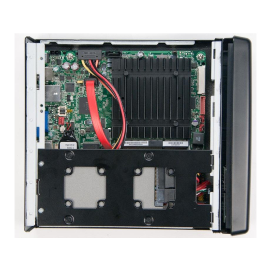
Page 102: Installing Ssd And Fans
Embedded Intel® Atom™ Processor N2800 with Intel® NM10 Express Chipset Development Kit User‘s Manual Installing SSD and Fans Install the SSD using the provided screws. The SSD (and optional coolers) will be fastened onto the SSD Mounting Bracket see Figure 31. On the bracket you can install one 2.5‖ hard drive or two fans (40x40x10mm) pictured below. -
Page 103: Operating System Reference
APIs across all target device types, and the flexibility to support add-ons and applications. Since Windows 7 is the exclusive property of Microsoft, Intel is legally not allowed to distribute a BSP or full OS image with Intel drivers already pre-installed in... -
Page 104: Table 53. Windows 7 Installation Options
Embedded Intel® Atom™ Processor N2800 with Intel® NM10 Express Chipset Development Kit User‘s Manual it. The purpose of this section is thus to provide the instructions necessary for downloading and creating the Microsoft Windows 7 OS and then installing the drivers created by Intel for this platform under Windows 7. -
Page 105: Downloading And Installing Processor, Graphics, Chipset And Other Optional Drivers
Embedded Intel® Atom™ Processor N2800 with Intel® NM10 Express Chipset Development Kit User‘s Manual 7.1.2 Downloading and installing processor, graphics, chipset and other optional drivers Though the standard OS may contain several drivers compatible with the platform it is recommended that you install the latest platform drivers found here: http://downloadcenter.intel.com/SearchResult.aspx?lang=eng&ProductFamily=Deskto... -
Page 106: Downloading, Burning, And Installing The Wes7 Dvd Image
Embedded Intel® Atom™ Processor N2800 with Intel® NM10 Express Chipset Development Kit User‘s Manual Standard 7 includes Windows Vista and Windows 7 features such as Aero, SuperFetch, ReadyBoost, BitLocker Drive Encryption, Windows Firewall, Windows Defender, Address space layout randomization, Windows Presentation Foundation, Silverlight 2, Windows Media Center among several other packages. -
Page 107: Figure 32: Build An Image
Embedded Intel® Atom™ Processor N2800 with Intel® NM10 Express Chipset Development Kit User‘s Manual Figure 32: Build an image 3. Read and accept the license as shown in Figure 33. Click Next Figure 33: Accept the license terms 4. WES7 allows you to choose from several pre-configured templates when creating your image. -
Page 108: Figure 34: View Template
Embedded Intel® Atom™ Processor N2800 with Intel® NM10 Express Chipset Development Kit User‘s Manual which installs many of the basic Windows applications (Media Player, Internet explorer, etc.) and drivers necessary for broad application support with the default windows desktop look and feel. Intel recommends that you click View Template on each as shown Figure 34. -
Page 109: Figure 36: Choose A Language And Other Preferences
Embedded Intel® Atom™ Processor N2800 with Intel® NM10 Express Chipset Development Kit User‘s Manual You may also choose Do not use a template to create your own customized image with only the drivers and features that you need for your specific product implementation. -
Page 110: Downloading And Installing Processor, Graphics, Chipset And Other Optional Drivers
Embedded Intel® Atom™ Processor N2800 with Intel® NM10 Express Chipset Development Kit User‘s Manual 8. The installation will run for several minutes. During this time, the system may restart a number of times. Figure 38: Installing Windows 9. When the install process completes, you will be presented with a login screen, where you can establish a user account and name for your system. -
Page 111: Installing Windows Embedded Compact 7
Embedded Intel® Atom™ Processor N2800 with Intel® NM10 Express Chipset Development Kit User‘s Manual http://downloadcenter.intel.com/SearchResult.aspx?lang=eng&ProductFamily=Deskto p+Boards&ProductLine=Intel%c2%ae+NM10+Chipset+Family+Boards&ProductProduct =Intel%c2%ae+Desktop+Board+DN2800MT&DownloadType=Drivers These drivers, in pre-release and release forms are also available in the same package format from https://platformsw.intel.com. Please see your Intel field representative for access. -
Page 112: F6 Install With Floppy
Embedded Intel® Atom™ Processor N2800 with Intel® NM10 Express Chipset Development Kit User‘s Manual early in the installation sequence. Additional information about this issue can be found on the Microsoft website. http://support.microsoft.com/kb/314859 http://support.microsoft.com/kb/916196 Note: Not all USB floppy disk drives are created equal. If you go this route, please read the above support documents from Microsoft to get a list of supported floppy drives. - Page 113 Embedded Intel® Atom™ Processor N2800 with Intel® NM10 Express Chipset Development Kit User‘s Manual c) Press S to Specify Additional Device. The SCSI adapter screen will appear.
- Page 114 Embedded Intel® Atom™ Processor N2800 with Intel® NM10 Express Chipset Development Kit User‘s Manual d) Press Enter to Select the Intel® NM10 Express Chipset. The screen titled ―Setup will load support for Intel® NM10 Express Chipset‖ will appear.
- Page 115 Embedded Intel® Atom™ Processor N2800 with Intel® NM10 Express Chipset Development Kit User‘s Manual e) Press Enter to continue. The partitions screen will appear.
-
Page 116: Slipstream Install
Embedded Intel® Atom™ Processor N2800 with Intel® NM10 Express Chipset Development Kit User‘s Manual f) Select the C: partition and press Enter. Setup will continue as normal. 7.4.3 Slipstream install There are several tools available that can create a slipstream image. This document uses the nLite* 1.4.9.1 tool. - Page 117 Embedded Intel® Atom™ Processor N2800 with Intel® NM10 Express Chipset Development Kit User‘s Manual Click on Browse and point to the folder with the Windows XP installation files (from step 4). You will see the information fields populate. Click Next.
- Page 118 Embedded Intel® Atom™ Processor N2800 with Intel® NM10 Express Chipset Development Kit User‘s Manual Browse to the Intel Rapid Storage Technology F6 Driver files. Select the iaAHCI.inf file. Select the Textmode driver radio button. Select the Intel® NM10 Express Chipset in the Textmode integration options pane.
-
Page 119: Install Device Drivers
Embedded Intel® Atom™ Processor N2800 with Intel® NM10 Express Chipset Development Kit User‘s Manual Name your ISO with a meaningful name, such as: WindowsXPSP3WithNM10Sata.iso Click Next. Click Finish. 6. Burn the newly generated ISO file to a CD using your favorite tool. -
Page 120: Using Meego
Embedded Intel® Atom™ Processor N2800 with Intel® NM10 Express Chipset Development Kit User‘s Manual Intel® EMGD is designed to work with fixed-function systems, such as Point-of-Sale (POS) devices, ATMs, gaming devices, In-vehicle Information/Entertainment systems, etc. It can be configured to work with various hardware and software systems. -
Page 121: Install With Usb Stick
Embedded Intel® Atom™ Processor N2800 with Intel® NM10 Express Chipset Development Kit User‘s Manual 3. Download and install Win32 Disk Imager from: https://launchpad.net/win32-image-writer/+download 4. Use Win32DiskImager to put the image on your USB Stick 5. Write the image to the USB stick by selecting Write. -
Page 122: Graphics Driver
Embedded Intel® Atom™ Processor N2800 with Intel® NM10 Express Chipset Development Kit User‘s Manual 5. Write the image to the USB stick by selecting Write. 6. Insert the USB stick into the CRB. 7. When you boot the BIOS be sure to select the USB stick as the primary boot drive. -
Page 123: Booting Yocto Project
Embedded Intel® Atom™ Processor N2800 with Intel® NM10 Express Chipset Development Kit User‘s Manual Intel platform based on the Intel Atom Processor N2600/D2700/N2800 paired with Intel NM10 Express Chipset. For customers evaluating or using the Development Kit as a basis for their embedded design, and Yocto Project * to develop a custom Linux* operating system, this is the primary guidance Intel provides for setting up the drivers and operating system. -
Page 124: Install With Usb Stick
Embedded Intel® Atom™ Processor N2800 with Intel® NM10 Express Chipset Development Kit User‘s Manual 6. Write the image to the USB stick by selecting Write. 7. Insert the USB stick into the CRB. 8. When you boot the BIOS be sure to select the USB stick as the primary boot drive. -
Page 125: Install With Cd Or Dvd
The preliminary Yocto Project* BSP graphics driver will be based on the standard Linux VESA driver. This VESA driver will not be able to take advantage of Intel‘s graphics engine. Closed source hardware accelerated graphics drivers will be incorporated into... -
Page 126: Battery Disposal Information
Embedded Intel® Atom™ Processor N2800 with Intel® NM10 Express Chipset Development Kit User‘s Manual Battery Disposal Information CAUTION Risk of explosion if the battery is replaced with an incorrect type. Batteries should be recycled where possible. Disposal of used batteries must be in accordance with local environmental regulations. - Page 127 Embedded Intel® Atom™ Processor N2800 with Intel® NM10 Express Chipset Development Kit User‘s Manual PRECAUCIÓN Existe peligro de explosión si la pila no se cambia de forma adecuada. Utilice solamente pilas iguales o del mismo tipo que las recomendadas por el fabricante del equipo.
- Page 128 Embedded Intel® Atom™ Processor N2800 with Intel® NM10 Express Chipset Development Kit User‘s Manual AWAS Risiko letupan wujud jika bateri digantikan dengan jenis yang tidak betul. Bateri sepatutnya dikitar semula jika boleh. Pelupusan bateri terpakai mestilah mematuhi peraturan alam sekitar tempatan.
- Page 129 Embedded Intel® Atom™ Processor N2800 with Intel® NM10 Express Chipset Development Kit User‘s Manual...
Need help?
Do you have a question about the Atom N2800 and is the answer not in the manual?
Questions and answers