Table of Contents
Advertisement
Quick Links
TECHNICAL MANUAL
Of
Intel D525 CPU + Intel NM10 Chipset
Based Mini-ITX M/B
NO. G03-NL10-I525-F
Revision: 1.0
nd
Release date: August 22
, 2013
Trademark:
* Specifications and Information contained in this documentation are furnished for information use only, and are
subject to change at any time without notice, and should not be construed as a commitment by manufacturer.
Advertisement
Table of Contents

Related Manuals for Intel D525


Summary of Contents for Intel D525
- Page 1 TECHNICAL MANUAL Intel D525 CPU + Intel NM10 Chipset Based Mini-ITX M/B NO. G03-NL10-I525-F Revision: 1.0 Release date: August 22 , 2013 Trademark: * Specifications and Information contained in this documentation are furnished for information use only, and are subject to change at any time without notice, and should not be construed as a commitment by manufacturer.
- Page 2 Environmental Protection Announcement Do not dispose this electronic device into the trash while discarding. To minimize pollution and ensure environment protection of mother earth, please recycle.
-
Page 3: Table Of Contents
TABLE OF CONTENT ENVIRONMENTAL SAFETY INSTRUCTION................iii USER’S NOTICE ........................iv MANUAL REVISION INFORMATION ..................iv ITEM CHECKLIST ........................iv CHAPTER 1 INTRODUCTION OF THE MOTHERBOARD FEATURE OF MOTHERBOARD................1 SPECIFICATION ......................2 LAYOUT DIAGRAM....................3 CHAPTER 2 HARDWARE INSTALLATION JUMPER SETTING ..................... -
Page 4: Environmental Safety Instruction
Environmental Safety Instruction Avoid the dusty, humidity and temperature extremes. Do not place the product in any area where it may become wet. 0 to 60 centigrade is the suitable temperature. (The figure comes from the request of the main chipset) Generally speaking, dramatic changes in temperature may lead to contact malfunction and crackles due to constant thermal expansion and contraction from the welding spots’... -
Page 5: User's Notice
USER’S NOTICE COPYRIGHT OF THIS MANUAL BELONGS TO THE MANUFACTURER. NO PART OF THIS MANUAL, INCLUDING THE PRODUCTS AND SOFTWARE DESCRIBED IN IT MAY BE REPRODUCED, TRANSMITTED OR TRANSLATED INTO ANY LANGUAGE IN ANY FORM OR BY ANY MEANS WITHOUT WRITTEN PERMISSION OF THE MANUFACTURER. -
Page 6: Chapter 1 Introduction Of The Motherboard Feature Of Motherboard
Introduction of the Motherboard Feature of Motherboard ® ® Intel ATOM D525 dual-core CPU+ Intel NM10 express chipset, with low power consumption never denies high performance Support 1 * DDRIII SO-DIMM 800 MHz up to 4GB Onboard RTL8111F Gigabit Ethernet LAN chip... -
Page 7: Specification
1-2 Specification Spec Description Mini-ITX form factor ; Design PCB size: 17.0 x 17.0 cm ® Intel D525 Dual Core CPU Embedded CPU ® Intel NM10 Express Chipset Chipset 1* DDRIII SO-DIMM slot Support DDRIII 800 MHz DDRIII SO-DIMM expandable to... -
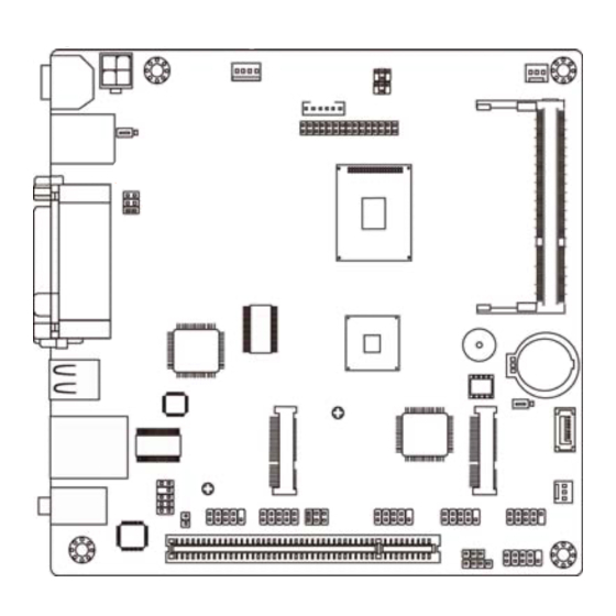
Page 8: Layout Diagram
Internal I/O Connectors& Headers: 1 *4-pin ATX12V Power connector 1 *4-pin SATA Power connector 1*CPU fan header 1*System fan header 1 * Front panel audio header 1 * HDMI_SPDIF header 3 * COM headers 1 *GPIO header 1 * 9-Pin USB 2.0/1.1 header for two USB 2.0/1.1 ports 1* Power LED header 1* Speaker header 1 * Front panel header... - Page 9 SATA Hard Disk PS/2 Keyboard Power-Out Connector over PS/2 Mouse Port DDRIII SODIMM Slot Intel CPU Parallel Port over Serial Port(COM1) Intel NM10 Chipset & VGA Port USB 2.0 Ports SATAII Port M-SATA (SATA1) Half-Size Hard Disk RJ-45 LAN Port Mini-PCIE Connector over USB 2.0 Ports...
- Page 10 Motherboard Jumper Position JBAT Jumper Jumper Name Description INVERTER VCC 3.3V/5V/12V Select 4-pin Block LVDS VCC 3.3V/5V/12V Select 4-pin Block JBAT CMOS RAM Clear Function Setting 3-pin Block K/B Power on Function Select 3-pin Block COM1 Port Pin9 Function Select 6-Pin Block COM2 Header Pin9 Function Select 6-Pin Block...
- Page 11 Connectors Connector Name DC12V1 DC 12V Power–in Connector ATX12V ATX 12V Power Connector KBMS PS/2 KB/MS Connector COM1 Serial Port Connector Video Graphic Attach Connector PARALLEL Parallel Port Connector USB 2.0 Port Connector x2 UL1(Middle & Bottom) USB 2.0 Port Connector x2 UL1(Top) RJ-45 LAN Connector AUDIO (Top)
-
Page 12: Chapter 2 Hardware Installation
Chapter 2 Hardware Installation 2-1 Jumper Setting (1) JP1 (4-pin): INVERTER VCC 3.3V/5V/12V Select 2 4 6 2 4 6 1 3 5 1 3 5 3-4 Closed: 2-4 Closed: 6-4 Closed: Inverter Backlight Inverter Backlight Inverter Backlight VCC= 5V; VCC= 3.3V;... - Page 13 (3) JBAT (3-pin): CMOS RAM Clear Function Setting JBAT 1-2 Closed: Normal; 2-3 Closed:Clear CMOS CMOS Clear Setting (4) JP5 (6-pin): K/B Power on Function Select 1-2 Closed: K/B Power on Disable; 2-3 Closed: K/B Power on Enabled...
- Page 14 (5) JP7 (6-pin): COM1 Port Header Pin9 Function Select 1-2 Closed: RS232; 3-4 Closed : +12V; 5-6 Closed : +5V (6) JP3 (6-pin): COM2 Header Pin9 Function Select 1-2 Closed: RS232; 5-6 Closed : +5V 3-4 Closed : +12V...
-
Page 15: Connectors And Headers
Connectors and Headers 2-2-1 Connectors (1) Rear IO Diagram Connectors PS/2 Mouse Port Parallel Port RJ-45 LAN Port Line-OUT DC12V Power-in MIC-IN Connector COM1 Port VGA Port USB 2.0 Ports PS/2 Keyboard Port (2) DC12V1 (4-pin Block): DC12V Power Connector Pin1 Pin2 Pin3... - Page 16 (3) ATX12V (4-pin block): ATX12V Type Power Connector Pin1 Pin No. Definition +12V +12V (4) SATA2:SATAII Port connector SATA2 port is a SATAII port that supports 3 GB/s transfer rate. Pin No. Defnition...
-
Page 17: Headers
(5) SATA Hard Disk Power-out Connector (4-pin): PWOUT1 Pin 1 2-2-2 Headers (1) FP_AUDIO1 (9-pin): Line-Out, MIC-In Header This header connects to Front Panel Line-out, MIC-In connector with cable. LINEOUT2-L S ENSE-FB LINE OUT2-R MIC2-R MIC2-L Pin 1... - Page 18 (2) HDMI_SPDIF(9-Pin): SPDIF_Out Header SPDIF-O UT Pin 1 (3) COM2/3/4 (9-Pin): Serial Port Headers Pin6 Pin1 Pin5 Serial Port Header...
- Page 19 (4) USB2 (9-pin): USB 2.0 Port Header Pin 1 (5) GPIO_CON (10-pin): GPIO Header Pin2 Pin1...
- Page 20 (6) PWRLED (3-pin): Power LED Header PWRLED Pin 1 (7) SPEAK (9-pin): Speaker Header SPEAK Pin 1...
- Page 21 (8) JW-FP1 (9-pin): Front Panel Header Pin 1 (9) LVDS (30-Pin): 18-bit single channel LVDS Header Pin2 Pin 30 Pin 1 Pin 29 LVDS Header...
- Page 22 Pin NO. Pin Define Pin NO. Pin Define Pin 1 LVDS_VCC Pin 2 LVDS_VCC Pin 3 LVDS_VCC Pin 4 Pin 5 Pin 6 Pin 7 LVDSA_DATAN0 Pin 8 LVDSA_DATAP0 Pin 9 LVDSA_DATAN1 Pin 10 LVDSA_DATAP1 Pin 11 LVDSA_DATAN2 Pin 12 LVDSA_DATAP2 Pin 13 Pin 14...
- Page 23 (12) CPUFAN (3-pin)/SYSFAN1 (3-pin): FAN Headers Pin1 CPUFAN Pin1 SYSFAN1 +12V Fan Power Fan Speed...
-
Page 24: Chapter 3 Introducing Bios
Chapter 3 Introducing BIOS Notice! The BIOS options in this manual are for reference only. Different configurations may lead to difference in BIOS screen and BIOS screens in manuals are usually the first BIOS version when the board is released and may be different from your purchased motherboard. Users are welcome to download the latest BIOS version form our official website. -
Page 25: Enterning Setup
Entering Setup Power on the computer and by pressing <Del> immediately allows you to enter Setup. If the message disappears before your respond and you still wish to enter Setup, restart the system to try again by turning it OFF then ON or pressing the “RESET” button on the system case. - Page 26 Figure 3-1 Standard BIOS Features Use this Menu for basic system configurations. Advanced BIOS Features Use this menu to set the Advanced Features available on your system. Advanced Chipset Features Use this menu to change the values in the chipset registers and optimize your system’s performance.
-
Page 27: Standard Bios Features
This entry shows your PC health status. Miscellaneous Control Use this menu to specify your settings for Miscellaneous Control. Load Optimized Defaults Use this menu to load the BIOS default values these are setting for optimal performances system operations for performance use. Load Standard Defaults Use this menu to load the BIOS default values for the minimal/stable performance system operation... - Page 28 System Date Use [Enter], [TAB] or [SHIFT-TAB] to select setting filed. Then use [+] or [-] to configure system date. The date format is <day><month><date><year>. Day of the week is from Sun to Sat, determined by BIOS. Read-only. Month The month is from Jan. through Dec. Date The date from 1 to 31 can be keyed by numeric function keys.
-
Page 29: Advanced Bios Features
Type: The optional settings are: [Not Installed]; [Auto]; [CD/DVD] and [ARMD]. LBA/Large Mode: The optional settings are [Auto]; [Disabled]. Disabled: disables LBA mode. Auto: enables LBA Mode if the devices support it and the device is not already formatted with LBA Mode disabled. Block (Multi-Sector Transfer): The optional settings are: [Disabled] and [Auto]. - Page 30 Virus Warning The selection Allow you to choose the VIRUS Warning feature for Hard Disk boot sector protection. If this function is enabled and someone attempt to write data into this area, BIOS will show a warning message on screen and alarm beep. Disabled (default) No warning message to appear when anything attempts to access the boot sector or hard disk partition table.
-
Page 31: Cpu Feature
3-5-1 CPU Feature Hyper Threading Technolegy Enabled for Windows XP and Linux4(OS optimized for Hyper Threading Technology) and disabled for other OS (OS not optimized for Hyper –Threading Technology). Limit CPU MaxUal The optional settings are: [Disabled]; [Enabled]. Please set is as ‘Disabled’ for WindowsXP OS. Execute Disable Bit Capabill The optional settings are: [Disabled];... - Page 32 DRAM Timing Settings by SPD The optional settings are: [Disabled]; [Enabled]. Initate Graphic Adapter The optional settings are: [IGD]; [PCI/IGD]. Select which graphic controller to use as the primary boot device. IGD Mode Select Use this item to select the amount of system memory used by the internal graphics device.
-
Page 33: Integrated Pheriphrals
Use this item to select flat panel resolution type. The optional settings are: [640X 480]; [800X 600]; [1024X768]; [800X480]; [1024X600]; [1366X768]; [1280X768]; [1280X800]; [1280X600]. Backlight Control Support The optional settings are: [VBIOS Default];[Both BLC & BIA Disabled];[BLC Enabled]. 3-7 Integrated Peripherals... -
Page 34: Onboard Sata Function
3-7-1 Onboard SATA Function Configure SATA as The optional settings are: [IDE]; [AHCI]. SATA Run Mode Configuration The optional settings are: [Compatible];[Enhanced]. -
Page 35: Onboard Device Function
3-7-2 Onboard Device Function Onboard LAN1 Controller The optional settings are: [Enabled]; [Disabled]. Onboard LAN1 BootROM The optional settings are: [Enabled]; [Disabled]. High Definition Audio The settings are: [Auto];[Disabled]. USB Host Controller The optional settings: [Enabled]; [Disabled]. USB 2.0 Function The optional settings: [Enabled];... -
Page 36: Onboard Super Io Function
The settings are: [FullSpeed]; [HiSpeed]. USB Keyboard Legacy Support Use these items to enable or disable legacy support for USB keyboard devices. The settings are: [Enabled], [Disabled]. USB Mouse Legacy Support Use these items to enable or disable legacy support for USB mouse devices. The settings are: [Enabled], [Disabled]. - Page 37 The optional settings are: [Disabled]; [3F8/IRQ4]; [3E8/IRQ4]; [2E8/IRQ3]. Serial Port 2 Address This item allows BIOS to select base addresses for serial port 2. The optional settings are: [Disabled]; [2F8/IRQ3]; [3E8/IRQ4]; [2E8/IRQ3]. Serial Port 3 Address This item allows BIOS to select base addresses for serial port 3. The optional settings are: [Disabled];...
-
Page 38: Power Management Setup
Power Management Setup The Power Management Setup allows you to configure your system to most effectively save energy saving while operating in a manner consistent with your own style of computer use. ACPI Suspend Type Users can select the ACPI state used for system suspend. The optional settings are: [S1(POS)];... - Page 39 Power Button Mode Use this item to go into [On/Off] or [Suspend] when power button is pressed. ERP Function The optional settings are: [Enabled]; [Disabled]. When set as [Disabled], the following sub-items shall appear: PWR Status after PWR Failure The optional settings: [Always Off]; [Always On]; [Former Status]. This function is supported when EUP Function is set as [Disabled].
-
Page 40: Pnp/Pci Configurations
3-9 PnP/PCI Configurations IRQ Resources Press [Enter] to view IRQ availability. Available: Specified IRQ is available to be used by PCI/PnP devices. Reserved: Specified IRQ is reserved for use by legacy ISA devices. PCI/VGA Palette Snoop The optional settings are: [Enabled]; [Disabled]. Enabled: to inform the PCI devices that an ISA graphics device is installed in the system so the card will function correctly. - Page 41 Shutdown Temperature This item can let users set the Shutdown temperature, when CPU temperature over this setting the system will auto shutdown to protect CPU. The optional settings are: [Disabled]; [60°C/140F]; [65°C/149F];[70°C/158F]; [75° C/167F]. CPU Thermal Throttling The optional settings are: [Disabled]; [Enabled]. *Note: When it is set as [Enabled], use can make settings for the following items that show up: CPU Thermal-Throttling Temp.;...
- Page 42 The optional settings are: [Disabled]; [Enabled]. ► Smart Fan Configuration CPUFAN / SYSFAN1 Smart Mode When set as [Enabled], the following sub-items shall appear: CPUFAN / SYSFAN1 Full Speed Temp Use this item to set a degree for CPUFAN/SYSFAN1. FAN will run at full speed when above the set temperature value.
-
Page 43: Miscellaneous Control
3-11 Miscellaneous Control Spread Spectrum The optional settings are: [Enabled]; [Disabled]. Linear PCIEX Clock The optional settings are from 100 to 200. DRAM Clock at Next Boot This item allows you to set DRAM clock. The optional settings are: [Auto]; [667MHz]; [800MHz]. Host/PCI Clock at Next Boot The optional settings are from 200 to 600. -
Page 44: Password Setting
3-12 Password Setting You can set either supervisor or user password, or both of them. The differences are: Supervisor password: Can enter and change the options of the setup menus. User password: Can only enter but do not have the right to change the options of the setup menus. -
Page 45: Load Optimized /Standarddefaults
3-13 Load Optimized /Standard Defaults Load Optimized Defaults When you press <Enter> on this item, you get a confirmation dialog box with a message similar to: Pressing <OK> loads the default values that are factory settings for optimal performance system operations. Load Standard Defaults When you press <Enter>... -
Page 46: Save And Exit Setup/Exit Without Saving
Exit Without Saving When you press <Enter> on this item, you get a confirmation dialog box with a message similar to: Pressing <OK> to leave BIOS setting without saving previously set values.
Need help?
Do you have a question about the D525 and is the answer not in the manual?
Questions and answers