Table of Contents
Advertisement
Quick Links
230V~ SMOKE & HEAT ALARMS
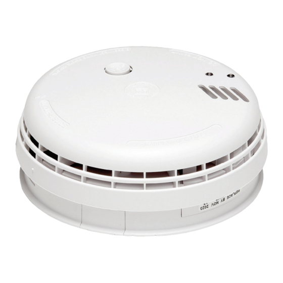
Introduction to EIB140RC
Smoke/Heat Alarms
The EIB140RC series is supplied with an Easi-Fit
base that allows very quick and simple installation
of the Smoke Alarm, combined with simple detector
head removal and replacement. The Easi-Fit base
automatically connects both mains power and battery
as the detector head slides on to the Easi-Fit base.
Up to 12 Smoke/Heat Alarms can be interconnected so
that when one senses fire all the units alarm.
Interconnection can be achieved by hardwire or through
a RadioLINK Base, the EIB168RC.
A green LED indicates the presence of mains power. A
red LED will flash rapidly in an alarm scenario.
All Alarms feature a combined test/hush button.
The "Test/Hush" button will either silence false alarms
or perform a unit self-test.
In "Test" mode the Alarm will perform a self-test and
sound the horn.
In "Hush" mode the Alarm will be silenced for a period
of approximately ten minutes to overcome false alarm
conditions. It will then automatically reset itself.
P/N B18866Rev1
EIB140RC Series
with Alkaline Battery Backup
Instruction Manual
User Section
© Brooks 2018
Advertisement
Table of Contents

Subscribe to Our Youtube Channel
Related Manuals for Ei Electronics EIB140RC Series


Summary of Contents for Ei Electronics EIB140RC Series
- Page 1 Instruction Manual User Section Introduction to EIB140RC Smoke/Heat Alarms The EIB140RC series is supplied with an Easi-Fit base that allows very quick and simple installation of the Smoke Alarm, combined with simple detector head removal and replacement. The Easi-Fit base automatically connects both mains power and battery as the detector head slides on to the Easi-Fit base.
-
Page 2: Changing The Battery
Brooks RadioLINK or RadioLINK products through fitting onto an EIB168RC RadioLINK Base. This base will enable the EIB140RC series Alarms to communicate RF messages to other Brooks products such as the EIB450 RadioLINK Alarm Controller where you can remotely locate, test and hush your EIB140RC Series Alarms using this wireless controller. -
Page 3: Testing And Maintenance
Testing and Maintenance Check all Alarms weekly, especially after initial installation or re-occupation (e.g. following a holiday) 1. Check that the green mains indicator light is on. (if it is off check circuit breakers, fuses and wiring etc.) 2. Check that the red LED on the cover flashes once every 40 seconds to indicate normal operation –... - Page 4 If the unit is beeping: Before replacing the battery, check that the beeps are not due to one of the following: (i) battery snaps not connected properly. (ii) On the Optical Smoke Alarm only (EIB146RC) if the unit beeps and the red light does not flash at the same time it indicates a problem with the smoke chamber - see “Cleaning Your Alarm”...
-
Page 5: Silence Feature
Check the house carefully in case there is a small fire smouldering somewhere. Check whether there is some source of smoke or fumes, for example cooking fumes being drawn past the Smoke Alarm by an extractor. If there are frequent nuisance/false alarms it may be necessary to re-locate the device away from the source of the fumes or replace an Ionisation Alarm with an Optical Alarm. -
Page 6: Service And Guarantee
3. Get out as fast as you can. Do not stop for packing. Have a prearranged meeting place outside for all family members. Check everybody is there. Call Fire Brigade immediately on a mobile phone or from a neighbour’s house. Make sure to call the Brigade for all fires no matter how small - fires can suddenly spread. - Page 7 the unit may beep or alarm in the post. State the nature of the fault, where the Alarm was purchased and the date of purchase. Brooks guarantees this Alarm to the original consumer purchaser for five years from date of purchase against any defects that are due to faulty materials or workmanship.
- Page 8 Conforms To AS3786:2014 Contact Us Brooks Australia PTY Ltd. 4 Pike Street, Rydalmere NSW 2116 Australia Tel: 0296841466 www.brooks.com.au Ei Electronics. Shannon, Co Clare, Ireland. Tel: 061 471277 www.eielectronics.com...
-
Page 9: Installer Section
Installer Section Installation Guide LOCATE CORRECT SITING POINT ALARM SHOULD BE CEILING MOUNTED AT LEAST 300mm FROM WALLS & OBSTRUCTIONS, IDEALLY CENTRALLY IN ROOM/AREA FIX & WIRE BASEPLATE WIRE TO TERMINALS ON THE BASEPLATE AND FIX BASEPLATE TO CEILING USING THE FIXINGS PROVIDED SLIDE ON ALARM SLIDE ALARM ONTO BASEPLATE. - Page 10 How Many Alarms To Install The minimum number of smoke Alarms is set out in the National Construction Code (NCC) Building Code of Australia: Volumes 1 and 2, and/or the relevant State or Territory Building Regulations. The main reason for fitting Smoke & Heat Alarms in dwellings is to ensure that when there is a fire, sufficient early warning is given so that everybody can escape safely.
- Page 11 Optical/Ionisation/Heat Alarm Selection Locations & Performance Alarm Type Optical Ionisation Heat Locations Hall, Corridors, Escape Routes Kitchens Living Rooms Bedrooms Shower / Bathroom Fire Response Slow Smouldering Fires (polyurethane foam, ignited bedding etc.) Fast Flaming Fires (chip pans, flaming wood/plastic, oil, solvents etc.) Temperature >58 (only in areas with cooking fumes, steam,...
-
Page 12: Positioning Alarms
Positioning Alarms he locations must comply with applicable building regulations. Hot smoke rises and spreads out, so a central ceiling position is the preferred location. The air is “dead” and does not move in corners, therefore Smoke & Heat Alarms must be mounted away from corners. -
Page 13: Installation
• Near a decorative object, door, light fitting, window moulding etc., that may prevent smoke or heat from entering the Alarm. • Surfaces that are normally warmer or colder than the rest of the room (e.g. attic hatches). Temperature differences might stop smoke or heat from reaching the unit. -
Page 14: Mounting & Wiring Alarms
WARNING: Mains operated Alarms should be installed and interconnected by a licensed electrician in accordance with the Australian wiring rules AS3000. Failure to install this Alarm correctly may expose the user to shock or fire hazards. WARNING: The Alarm must be continuously powered 24 hours a day so it is important that it is not on a circuit that can be turned off by a switch. - Page 15 4. If the mains wires are recessed, bring the wires through the rear hole in the mounting plate as shown in Figure 4. If the mains wires are being brought along the surface: (a) position the mounting plate so the cable trunking is as shown in Figure 4.
-
Page 16: Interconnecting Alarms
Interconnecting Alarms Note: A maximum of twelve EIB141RC / EIB144RC / EIB146RC Smoke or Heat Alarms may be interconnected. Up to 8 additional accessories may also be connected. If you wish to connect more than 12 Alarms contact your local distributor. Systems using more than 3 or 4 Alarms must be very carefully planned to ensure nuisance/false alarms are not excessive.
Need help?
Do you have a question about the EIB140RC Series and is the answer not in the manual?
Questions and answers
brooks eib146rc keeps going off there4 is a controller in the hall but it appears to not work
The Ei Electronics EIB140RC Series alarm may keep going off because it is interconnected with other alarms. If the controller in the hall is not working, it may not be transmitting or receiving the signal properly. Possible reasons include:
1. Faulty or incorrect wiring connections between alarms.
2. The hall controller may not be correctly connected or functioning.
3. The defective controller may prevent the system from silencing or testing alarms properly.
Check that all alarms are correctly interconnected and consider consulting a licensed electrician.
This answer is automatically generated