Table of Contents
Advertisement
Quick Links
230V~ SMOKE & HEAT ALARMS
Introduction to Ei160e
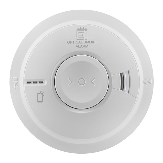
Smoke/Heat Alarms
The Ei160e series is supplied with an Easi-Fit base that
allows very quick and simple installation of the Smoke
Alarm, combined with simple detector head removal
and replacement. The Easi-Fit base automatically
connects both mains power and battery as the detector
head slides on to the Easi-Fit base.
Up to 12 Smoke/Heat Alarms can be interconnected so
that when one senses fire all the units alarm.
Interconnection can be achieved by hardwire or through
a modular RF module, the Ei100MRF, which can be
inserted into the base of the Alarm.
A green LED indicates the presence of mains power. A
red LED will flash rapidly in an alarm scenario.
The Smoke Alarms feature a large combined test/hush
button. The Heat Alarm features a test button.
The "Test/Hush" button will either silence false alarms
or perform a unit self-test.
In "Test" mode the Alarm will perform a self-test and
sound the horn.
In "Hush" mode the Alarm will be silenced for a period
of approximately ten minutes to overcome false alarm
conditions. It will then automatically reset itself.
P/N B18148 Rev0
Ei160e Series
with Rechargeable Battery Backup
Instruction Manual
User Section
© Ei Electronics 2015
Advertisement
Table of Contents

Related Manuals for Ei Electronics Ei161e


Summary of Contents for Ei Electronics Ei161e
- Page 1 In “Test” mode the Alarm will perform a self-test and sound the horn. In “Hush” mode the Alarm will be silenced for a period of approximately ten minutes to overcome false alarm conditions. It will then automatically reset itself. © Ei Electronics 2015 P/N B18148 Rev0...
- Page 2 Ei100MRF RadioLINK Module. This module will enable the Ei160e series alarms to communicate RF messages to other Ei Electronics products such as the Ei450 RadioLINK Alarm Controller where you can remotely locate, test and hush your Ei160e Series Alarms using this wireless controller.
- Page 3 5. Interconnected Alarms only - Test the first unit by pressing the button for 10 seconds. All the units should alarm within 10 seconds of the first horn sounding. The red light on the first unit only will flash about once a second. On releasing the button the local Alarm will stop sounding immediately and the remote Alarms will stop sounding approximately 3 seconds later (if testing using RF interconnection...
-
Page 4: Silence Feature
Use the narrow nozzle attachment of your vacuum cleaner to remove dust, insects and cobwebs from the sides and cover slots where the smoke or heat enters. To clean the cover, wipe with a damp cloth. Dry cover thoroughly with a lint free cloth. WARNING: Do not paint your Alarm. - Page 5 The unit will flash the red light every 10 seconds (instead of the normal 40 seconds) to indicate the sensitivity is reduced. On interconnected Alarms, pressing the Test/Silence Button on the one sensing smoke (i.e. the one with the red light flashing every second) will silence all alarms. Pressing the Silence Button on any other Alarm will not silence the alarm.
- Page 6 State the nature of the fault, where the Alarm was purchased and the date of purchase. Ei Electronics guarantees this Alarm for five years from date of purchase against any defects that are due to faulty materials or workmanship. This guarantee only...
-
Page 7: Troubleshooting
Do not interfere with the Alarm or attempt to tamper with it. This will invalidate the guarantee, but more importantly may expose the user to shock or fire hazards. This guarantee is in addition to your statutory rights as a consumer. Troubleshooting 1. - Page 8 For more details on collection and proper disposal, please contact your local government office or the retailer where you purchased this product. 0086 Ei Electronics, Shannon, Co. Clare, Ireland DoP No.15-0005 EN14604:2005 + AC:2008 Smoke Alarm Devices: Ei161e, Ei166e...
-
Page 9: Installer Section
Installer Section Installation Guide LOCATE CORRECT SITING POINT ALARM SHOULD BE CEILING MOUNTED AT LEAST 300mm FROM WALLS & OBSTRUCTIONS, IDEALLY CENTRALLY IN ROOM/AREA FIX & WIRE BASEPLATE WIRE TO TERMINALS ON THE BASEPLATE AND FIX BASEPLATE TO CEILING USING THE FIXINGS PROVIDED SLIDE ON ALARM SLIDE ALARM ONTO BASEPLATE. - Page 10 How Many Alarms To Install - Categories & Grades The advice here follows the guidance in British Standard BS 5839-6: 2013 in general (for further information see the BS standard itself). The main reason for fitting Smoke & Heat Alarms in dwellings is to ensure that when there is a fire, sufficient early warning is given so that everybody can escape safely.
-
Page 11: Selecting Alarm Type
Selecting Alarm Type Optical/Ionisation/Heat Alarm Selection Locations & Performance Alarm Type Optical Ionisation Heat Locations Hall, Corridors, Escape Routes Kitchens Living Rooms Bedrooms Shower / Bathroom Fire Response Slow Smouldering Fires (polyurethane foam, ignited bedding etc.) Fast Flaming Fires (chip pans, flaming wood/plastic, oil, solvents etc.) Temperature >58 (only in areas with cooking fumes, steam,... -
Page 12: Locations To Avoid
Positioning Alarms he locations must comply with applicable building regulations. Hot smoke rises and spreads out, so a central ceiling position is the preferred location. The air is “dead” and does not move in corners, therefore Smoke & Heat Alarms must be mounted away from corners. -
Page 13: Installation
• Near a decorative object, door, light fitting, window moulding etc., that may prevent smoke or heat from entering the Alarm. • Surfaces that are normally warmer or colder than the rest of the room (e.g. attic hatches). Temperature differences might stop smoke or heat from reaching the unit. -
Page 14: Mounting & Wiring Alarms
Note: BS 5839-6: 2013 gives the folowing recommendations regarding the mains supply to be used in a Grade D system (The Ei161e, Ei166e Smoke Alarms and Ei164e Heat Alarms can be used in a Grade D system). The power supply for the Alarms should be derived from the public electricity supply to the dwelling. - Page 15 • check for Live and Neutral using a two probe tester. • check for Live using a neon tester. • check that the Interconnect wire is NOT connected to Live, Neutral or Earth. Do not use an Earth wire for the Interconnect line.
-
Page 16: Interconnecting Alarms
Ensure the alarm operates correctly - see “TESTING & MAINTENANCE” section on page 2. Interconnecting Alarms Note: A maximum of twelve Ei161e / Ei164e / Ei166e Smoke or Heat Alarms may be interconnected. Up to 8 additional accessories may also be connected.
Need help?
Do you have a question about the Ei161e and is the answer not in the manual?
Questions and answers