Table of Contents
Advertisement
230V~ SMOKE & HEAT ALARMS
Introduction to EIB160e
Smoke/Heat Alarms
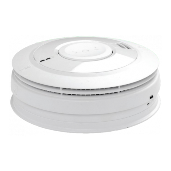
The EIB160e series is supplied with an Easi-Fit base that
allows very quick and simple installation of the Smoke
Alarm, combined with simple detector head removal
and replacement. The Easi-Fit base automatically
connects both mains power and battery as the detector
head slides on to the Easi-Fit base.
Up to 12 Smoke/Heat Alarms can be interconnected
so that when one senses fire all the units alarm. (More
Alarms can be interconnected. Please contact your
local distributor for more information.)
Interconnection can be achieved by hardwire or through
a modular RF module, the EIB100MRF, which can be
inserted into the base of the Alarm.
A green LED indicates the presence of mains power. A
red LED will flash rapidly in an alarm scenario.
The Smoke/Heat Alarms feature a large combined test/
hush button.
The "Test/Hush" button will either silence false alarms
or perform a unit self-test.
In "Test" mode the Alarm will perform a self-test and
sound the horn.
In "Hush" mode the Alarm will be silenced for a period
of approximately ten minutes to overcome false alarm
conditions. It will then automatically reset itself.
P/N B18646 Rev1
EIB160e Series
with Rechargeable Battery Backup
Instruction Manual
User Section
© Brooks 2018
Advertisement
Table of Contents

Related Manuals for Ei Electronics BROOKS EIB160e Series


Summary of Contents for Ei Electronics BROOKS EIB160e Series
- Page 1 EIB160e Series 230V~ SMOKE & HEAT ALARMS with Rechargeable Battery Backup Instruction Manual User Section Introduction to EIB160e Smoke/Heat Alarms The EIB160e series is supplied with an Easi-Fit base that allows very quick and simple installation of the Smoke Alarm, combined with simple detector head removal and replacement.
-
Page 2: Testing And Maintenance
RF Interconnection The EIB160e series may be interconnected with any other RadioLINK or RadioLINK products through inserting the EIB100MRF RadioLINK Module. This module will enable the EIB160e series Alarms to communicate RF messages to other products such as the EIB450 RadioLINK Alarm Controller where you can remotely locate, test and hush your EIB160e Series Alarms using this wireless controller. - Page 3 cobwebs or dust and clean the Alarm as described in the “cleaning” section if necessary. 5. Interconnected Alarms only - Test the first unit by pressing the button for 10 seconds. All the units should alarm within 10 seconds of the first horn sounding.
-
Page 4: Silence Feature
Cleaning WARNING: Electrical shock hazard. Disconnect the AC mains at the fuse box or circuit breaker powering the Alarm before following the cleaning instructions. Clean your Alarm regularly, particularly in dusty areas. Use the narrow nozzle attachment of your vacuum cleaner to remove dust, insects and cobwebs from the sides and cover slots where the smoke or heat enters. - Page 5 The unit will flash the red light every 10 seconds (instead of the normal 40 seconds) to indicate the sensitivity is reduced. On interconnected Alarms, pressing the Test/Silence Button on the one sensing smoke (i.e. the one with the red light flashing every second) will silence all Alarms. Pressing the Test/Silence Button on any other Alarm will not silence the Alarms in the system.
-
Page 6: Service And Guarantee
Limitations of Smoke / Heat Alarms Smoke / Heat Alarms have significantly helped to reduce the number of fire fatalities in countries where they are widely installed. However independent authorities have stated that they may be ineffective in some circumstances. There are a number of reasons for this: •... -
Page 7: Troubleshooting
Do not interfere with the Alarm or attempt to tamper with it. This will invalidate the guarantee, but more importantly may expose the user to shock or fire hazards. This guarantee is in addition to your statutory rights as a consumer. Troubleshooting 1. - Page 8 Certified To AS3786 2014 Contact Us Brooks Australia PTY Ltd. 4 Pike Street, Rydalmere NSW 2116 Australia Tel: 0296841466 www.brooks.com.au Ei Electronics. Shannon, Co Clare, Ireland. Tel: 061 471277 www.eielectronics.com...
-
Page 9: Installer Section
Installer Section Installation Guide LOCATE CORRECT SITING POINT ALARM SHOULD BE CEILING MOUNTED AT LEAST 300mm FROM WALLS & OBSTRUCTIONS, IDEALLY CENTRALLY IN ROOM/AREA FIX & WIRE BASEPLATE WIRE TO TERMINALS ON THE BASEPLATE AND FIX BASEPLATE TO CEILING USING THE FIXINGS PROVIDED SLIDE ON ALARM SLIDE ALARM ONTO BASEPLATE. - Page 10 How Many Alarms To Install The minimum number of smoke Alarms is set out in the National Construction Code (NCC) Building Code of Australia: Volumes 1 and 2, and/or the relevant State or Territory Building Regulations. The main reason for fitting Smoke & Heat Alarms in dwellings is to ensure that when there is a fire, sufficient early warning is given so that everybody can escape safely.
- Page 11 Optical/Ionisation/Heat Alarm Selection Locations & Performance Alarm Type Optical Ionisation Heat Locations Hall, Corridors, Escape Routes Kitchens Living Rooms Bedrooms Shower / Bathroom Fire Response Slow Smouldering Fires (polyurethane foam, ignited bedding etc.) Fast Flaming Fires (chip pans, flaming wood/plastic, oil, solvents etc.) Temperature >58 (only in areas with cooking fumes, steam,...
-
Page 12: Positioning Alarms
Positioning Alarms he locations must comply with applicable building regulations. Hot smoke rises and spreads out, so a central ceiling position is the preferred location. The air is “dead” and does not move in corners, therefore Smoke & Heat Alarms must be mounted away from corners. -
Page 13: Installation
• Near a decorative object, door, light fitting, window moulding etc., that may prevent smoke or heat from entering the Alarm. • Surfaces that are normally warmer or colder than the rest of the room (e.g. attic hatches). Temperature differences might stop smoke or heat from reaching the unit. -
Page 14: Mounting & Wiring Alarms
WARNING: Mains operated Alarms should be installed and interconnected by a licensed electrician in accordance with the Australian wiring rules AS3000. Failure to install this Alarm correctly may expose the user to shock or fire hazards. WARNING: The Alarm must be continuously powered 24 hours a day so it is important that it is not on a circuit that can be turned off by a switch. - Page 15 If the mains wires are being brought along the surface: (a) position the mounting plate so the cable trunking is as shown in Figure 4. Figure 4 (b) the mounting plate has a removable section, take it out to interface directly with 25mm conduit as shown in Figure 5.
-
Page 16: Interconnecting Alarms
Interconnecting Alarms Note: A maximum of twelve EIB161e / EIB164e / EIB166e / EIB166e DHHS Smoke or Heat Alarms may be interconnected. Up to 8 additional accessories may also be connected. If you wish to connect more than 12 Alarms contact your local distributor.
Need help?
Do you have a question about the BROOKS EIB160e Series and is the answer not in the manual?
Questions and answers