Table of Contents
Advertisement
Quick Links
Advertisement
Table of Contents

Related Manuals for Promax CompactMax-1


Summary of Contents for Promax CompactMax-1
- Page 1 CompactMax-1 DVB-S/S2 TO DVB-T TRANSMODULATOR - 0 MI2032 -...
- Page 3 SAFETY NOTES Read the user’s manual before using the equipment, mainly "SAFETY RULES" paragraph. The symbol on the equipment means "SEE USER’S MANUAL". In this manual may also appear as a Caution or Warning symbol. WARNING AND CAUTION statements may appear in this manual to avoid injury hazard or damage to this product or other property.
- Page 4 SAFETY REQUIREMENTS The security can be compromised if not applied the instructions in this manual. Remember that voltages higher than 70 V DC or 33 V AC rms are dangerous. Use this instrument under the specified environmental conditions. The user is not allowed to perform changes inside the equipment. Any change on the equipment must be done exclusively by specialized staff.
- Page 5 Symbols related with safety: Descriptive Examples of Over-Voltage Categories Cat I Low voltage installations isolated from the mains. Cat II Portable domestic installations. Cat III Fixed domestic installations. Cat IV Industrial installations.
-
Page 6: Table Of Contents
T A B L E O F C O N T E N T S INTRODUCTION ................... 1 1.1 Description ................1 PACKAGE CONTENT ................3 DESCRIPTION AND LOCATION ELEMENTS ........... 4 ASSEMBLY INSTRUCTIONS ..............6 4.1 Rack mounting ................6 4.2 Wall Mounting ................ -
Page 8: Introduction
Satellite TV channels (DVB-S or DVB-S2) in Digital Terrestrial Television (DVB-T) format. The CompactMax-1 has 4 satellite inputs. Two inputs are for free channels and the other two inputs for encrypted channels. There are also two slots to insert a Card Access Module (CAM) to decrypt these channels and one input for RF loopthrough. - Page 9 It can be used in hotels, convention centres, hospitals, ships, emblematic buildings, mansions, etc. Figure 1. June 2021...
-
Page 10: Package Content
2 PACKAGE CONTENT Main Unit. Quick guide. Power line. June 2021... -
Page 11: Description And Location Elements
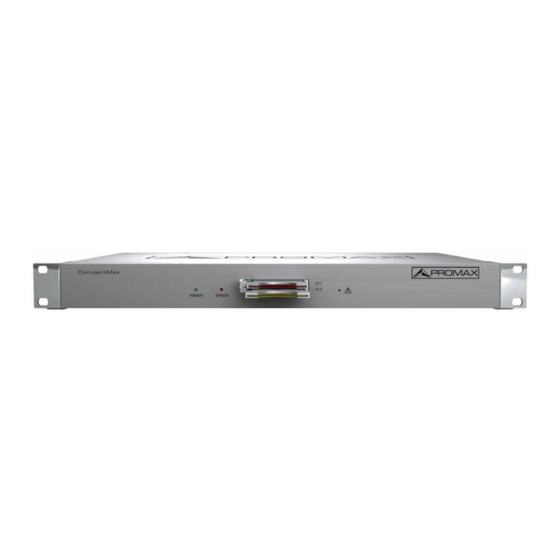
3 DESCRIPTION AND LOCATION ELEMENTS Front view Figure 2. Power On indicator. Error indicator. Common Interface input (CI#1) for decoder card. Common Interface input (CI#2) for decoder card. IP address reset. June 2021... - Page 12 Rear view Figure 3. Not in use. Ethernet connection equipment control default: 192.168.29.30; user: Admin; password: Admin). Input #4 for satellite signal (DVB-S/S2) free channels. Input #3 for satellite signal (DVB-S/S2) free channels. 10. Input satellite signal (DVB-S/S2) scrambled channels (connected to CI#2).
-
Page 13: Assembly Instructions
4 ASSEMBLY INSTRUCTIONS Rack mounting Figure 4. Wall Mounting Figure 5. June 2021... -
Page 14: Webserver Operation
5 WEBSERVER OPERATION Introduction The transmodulator is controlled and configured via Ethernet using a standard browser. The webserver application provides access to the setting parameters of the modulator. To use it you need just a standard browser and an internet connection. - Page 15 • Recovering the default IP If you do not remember or do not know the module IP follow the steps below: Press the reset button of the IP address (see figure 2 – (5)). The error LED will flash. Press and hold the button until the LED stops blinking.
-
Page 16: Screen Description
Screen description After logging, the following screen displays. Figure 6. Each screen has 4 specific areas: Tab area: Each tab access to a specific set of parameters. Setting Parameters area: Set of parameters according to the tab selected. Edit options: Options to edit parameters. Status area: Transmodulator current state. -
Page 17: Edit Options
Receivers: It shows the status (enabled/disabled) for the 4 satellite receivers. The radio button shows which one is working. CI modules: It shows the status (initialized/no card) for the CAM module inserted in the common interface (CI) slot. It also shows the satellite receiver selected and the number of selected services for each card. -
Page 18: Setting Parameters
Setting parameters Setting parameters are grouped in these tabs: Versions/store: Information about firmware versions and options to store/reset/reboot. Control: Network, password and language settings. Logs: Information about transmodulator operation. Receivers: Satellite receivers settings. CAM: Conditional Access Module (CAM) settings. Input Services: Information about services captured from satellite receivers. -
Page 19: Versions / Store
5.6.1 Versions / Store This window gives information about firmware versions and options to store/reset/reboot. Figure 8. Versions area: It shows information about firmware versions for different components of the transmodulator. Internal IDs area: It shows information about the identification number of the equipment, name and hardware. -
Page 20: Control
5.6.2 Control This window has some settings to connect to a data network, to change the password and the menu language. Figure 9. MAC: Physical address of the transmodulator. IP: IP address of the transmodulator in the network (IP by default 192.168.29.30). -
Page 21: Logs
5.6.3 Logs This window gives information about the transmodulator operation. Each event happening in the modulator is captured and shown on this window. Each event has a description, a tag and an identification number. Figure 10. June 2021... -
Page 22: Receivers
5.6.4 Receivers This window has some settings to tune the satellite signal. When the satellite signal is locked, it shows information about it. Figure 11. In first place, select one or two SAT inputs (from 1 to 4) to work on. Then expand the data tree. -
Page 23: Cam
5.6.5 In this window user can browse through the CAM module menu. Figure 12. Each time an option is selected, user should wait until the module access the next menu or option. Each CAM module has its own menu settings. June 2021... -
Page 24: Input Services
5.6.6 Input Services This window gives information about services captured from satellite receivers. Figure 13. Select the same SAT inputs than selected in the “Receivers” tab. Then expand the data tree to check information about the services captured. Available information is: Transport stream identifier: It is a number that identifies the transport stream. -
Page 25: Output Services
5.6.7 Output Services This window gives information about services to be released on the RF output. Figure 14. Select the RF output (RF 1 to RF 8) to work on. Then expand the data tree to set the parameters in order to release services at the output: Network identifier: It is the number that identifies the network where the signal is distributed. -
Page 26: Lcns
5.6.8 LCNs This window allows user to select the logical channel number (LCN) for each service selected. Figure 15. LCN: Logical channel number is the number that specifies the index to sort services on the digital terrestrial television receiver. There is also one option to auto number all services by filling the “First LCN” box and clicking on “Auto number”. -
Page 27: Dvb-T Modulators
5.6.9 DVB-T modulators This window shows RF output settings in order to distribute services in DVB-T format. Figure 16. Select the same RF outputs than selected in the “Output services” tab. Then expand the data tree to set the parameters in order to release services at the output. -
Page 28: Specifications
6 SPECIFICATIONS Specifications CompactMax-1 SATELLITE INPUTS 4 satellite inputs Typical LO frequencies 9750 MHz, 10600 MHz Supply External/+13 (vert.pol.)/+18 V (hor.pol.), 5 W each satellite input (max.) 22 kHz signalling Low/high frequency band Indicators Over/under load/current and malfunction IF frequency range 950 MHz to 2150 MHz (LNB LO freq ±downlink freq) -
Page 29: Maintenance
7 MAINTENANCE Instructions for returning by mail Instruments returned for repair or calibration, either within or out of the warranty period, should be sent with the following information: Name of the Company, name of the contact person, address, telephone number, receipt (in the case of coverage under warranty) and a description of the problem or the service required.
Need help?
Do you have a question about the CompactMax-1 and is the answer not in the manual?
Questions and answers