Table of Contents
Advertisement
Advertisement
Table of Contents

Related Manuals for Field Tuff ATV-3665


Summary of Contents for Field Tuff ATV-3665
- Page 1 ATV / LAWN TRACTOR TOWABLE TILLER Owner’s Manual ! WARNING: Carefully read and understand all ASSEMBLY AND OPERATION INSTRUCTIONS before operating. Failure to follow the safety rules and other basic safety precautions may result in serious injury. Item# ATV-3665 07132017...
-
Page 2: Intended Use
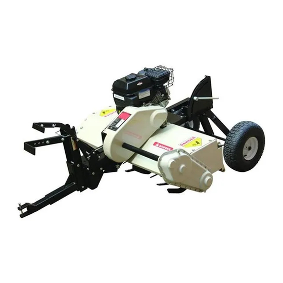
INTENDED USE The ATV-3665 ATV Tiller has twenty-four 12 inch hardened steel tines for tilling compacted soil. It is constructed with a manual lever for height adjustment up to 5 inches. The shock absorbing hitch and 15 inch pneumatic turf tires work well on uneven terrain. -
Page 3: Work Area
WORK AREA • Keep work area clean, free of clutter and well-lit. Cluttered and dark work areas can cause accidents. • Keep children and bystanders away while operating a Tiller. Distractions can cause you to lose control, so visitors should remain at a safe distance from the work area. •... - Page 4 SAFTY RULES Hazard Signal Word Definitions This is the safety alert symbol. It is used to ! alert you to potential personal injury hazards. Obey all safety messages that follow this symbol to avoid possible injury or death. DANGER indicates an imminent !...
- Page 5 SAFTY RULES ! WARNING Read this manual. Serious injury or death can result if safety instructions are not followed. Engine is shipped without oil. -Before starting engine, fill with SAE 10W-30 motor oil. -See engine manual for engine oil capacity. Closely inspect all Tiller components.
-
Page 6: Equipment Safety Guidelines
SAFTY RULES EQUIPMENT SAFETY GUIDELINES Safety of the operator and bystanders is one of the main concerns in designing and developing a tiller. However, every year accidents occur which could have been avoided by a few seconds of thought and a more careful approach to handling equipment. -
Page 7: Specification
SPECIFICATION Engine (see Engine manual for all specs) Briggs & Stratton XR 208cc; 6.5HP Approximate run time, one tank of fuel 3 Hours Chain/Gear box oil capacity 80W–90 gear oil; 1 quart (0.9 liter) Towing hitch type Pin Hitch Height adjustment Lift Lever Towing speed recommended 2 to 4 mph... - Page 8 ASSEMBLY INSTRUCTIONS Step 1: Wheel Assembly Attach the Wheel Bushing (#35) to the Wheel Axle (#36), then attach the Wheel (#34) to the Wheel Axle using one Wheel Bushing B (#33), one Flat Washer (#32) and one Cotter Pin (#31). Repeat this step for the other wheel.
- Page 9 ASSEMBLY INSTRUCTIONS Step 3: Lift Arm Assembly 1. Connect the Lift Arm (#92), the Connecting Plate (#64), and the Connecting Rod (#85) using two Nylon Washers (#80), two Big Flat Washers (#12), two Hex Bolts (#79), and two Nylon Lock Nuts (#10). See Figure 3.
-
Page 10: Safety Training
OPERATION INSTRUCTIONS SAFETY TRAINING Safety is a primary concern in the design and manufacturing of our Tiller. Unfortunately, our efforts to provide safe equipment can be wiped out by a single careless act of an operator or bystander. In addition to the design and configuration of equipment, hazard control and accident prevention are dependent upon the awareness, concern, prudence and proper training of personnel involved in the operation, transport, maintenance and storage of this equipment. - Page 11 OPERATION INSTRUCTIONS Operating the Tiller 1. Raise the Tiller Tines by making sure the Lift Arm is forward, then place the Tiller on level ground. Figure 5 shows the Tiller in the towing position (non-tilling position). 2. Disengage the Tine Clutch Lever, lock the Limiting Plate with the wheels in the raised position, then start the Engine following the procedure in the Engine Owner’s Manual.
-
Page 12: Maintenance And Storage
WARNING: Recommended Towing Speed is approx. 2 to 4 mph; depending on soil type and soil conditions. TEST RUN TILLER BEFORE USE: Position tiller so tines are fully in raised position. Start the engine, then engage tines. Allow tines to rotate for approx. 5 minutes. Dis-engage tines, then stop the engine and re-check following: Pulleys &... - Page 13 Regular Maintenance Checklist Before Every 20 Every 35 Every 50 Every 80 Procedure Each Use Hours Hours Hours Hours ● Check the engine oil level ● Clean the tines and debris shield Check the general condition of the ● machine, i.e. nuts ,bolts, weld, etc. ●...
- Page 14 MAINTENANCE AND STORAGE Please check if these two bolts are tightened. Figure 7 Replacing the Tine Drive Belt 1. Remove the Belt Cover. 2. Disengage the Tine Clutch Lever and remove the worn Belt. 3. Install a new Belt, engage the Tine Clutch Lever, attach the Belt Cover. Figure 8 Figure 9...
- Page 15 MAINTENANCE AND STORAGE Replacing the oil in chain/gear box The amount of oil needed: 1 Quart. 1. Place the tiller on a level surface and initially add 30 oz. (0.9 Quarts) of 80W-90 gear oil, and wait a minute for the oil to settle. 2.
-
Page 16: Troubleshooting
TROUBLESHOOTING SYMPTOM POSSIBLE CAUSE Recoil will not pull out or is Check that the tine drive clutch is disengaged. difficult to pull. Check the engine oil level; the engine may be seized. There may be an oil compression lock in the cylinder. Take out the spark plug; hold a rag over the spark plug hole and pull the recoil cord several times to blow out any oil in the cylinder. - Page 17 TROUBLESHOOTING Belt slips on pulley or Check that Belt and pulley are aligned properly. Belt comes off pulley Adjust the space of Nylon Lock Nuts M8. (See Figure 11 below) Belt Pulley Nylon Lock Nut M8 Figure 11...
- Page 18 PARTS LISTING & BREAKDOWN DRAWING Main Assembly-Exploded Drawing...
-
Page 19: Parts List And Parts Diagram
PARTS LIST and PARTS DIAGRAM Main Assembly-Parts List PART # DESCRIPTION QTY PART# DESCRIPTION Engine Wheel Axle Hex Bolt M6x45 Lock Washer Ø14 Big Flat Washer Ø6 Connecting Rod Nylon Lock Nut M6 Hex Bolt M12x55 Hex Bolt M6x14 Nylon Lock Nut M12 Lock Washer Ø6 Hex Nut M14 Cover Assy. - Page 20 Latch Spring Hex Bolt M10x30 Swing Plate Lift Handle Pull Rod Lock Pin A Nylon Lock Nut M10 Lift Arm Pulley Casing Bolt Ø9x87 Latch Spring R Pin Hex Bolt M8x16 Flat Washer Ø14 Lock Washer Ø8 Cotter Pin Ø3x30 Hex Bolt M8x25 Bushing Hexagon Socket Head Bolt...
- Page 21 PARTS LISTING & BREAKDOWN DRAWING Tine Drive Transmission Assembly- Exploded Drawing Tine Drive Transmission Assembly-Parts List Ref# Description Lock Washer Ø6 Nylon Lock Nut M6 Right Side Drive Housing Long Chain Gland Bush Frame-rubber Oil Seal Bearing Output Shaft Nylon Sleeve 2 Left Side Drive Housing Oil Plug A Hex Bolt M6x16...
- Page 22 PARTS LISTING & BREAKDOWN DRAWING Left Fender Assembly- Exploded Drawing Left Fender Assembly-Parts List Ref# Description Hex Bolt M6x16 Lock Washer Ø6 Flat Washer Ø6 Bearing Cover Shaft 4 Bearing Frame-rubber Oil Seal Left Fender...
- Page 23 PARTS LISTING & BREAKDOWN DRAWING Left Fender Assembly- Exploded Drawing Engine-Parts List Ref# Description Engine Bushing Flat Key Hex Bolt M6x16 Belt Pulley Big Flat Washer Ø8 Belt Gear Lever Lock Washer Ø8 Hex Bolt M8x20 For replacement parts and technical questions, please call 1-218-943-6296.
- Page 24 PARTS LISTING & BREAKDOWN DRAWING Pulley Assembly-Parts List PART# DESCRIPTION PART# DESCRIPTION Nylon Lock Nut M8 Bearing Bolt Pulley Ø78xØ24x27 Bracket Circlip for hole Ø26 Pulley Assembly-Exploding Drawing...
-
Page 25: Warranty
WARRANTY One-year limited parts warranty. PO BOX 203 Miltona, MN 56354 Made in China...
Need help?
Do you have a question about the ATV-3665 and is the answer not in the manual?
Questions and answers