Table of Contents
Advertisement
Quick Links
Advertisement
Table of Contents

Related Manuals for Siemens 8BT2


Summary of Contents for Siemens 8BT2
- Page 1 Medium-Voltage Switchgear Type 8BT2 Extendable Truck- Type Circuit-Breaker Switchgear up to 36kV Metal-Enclosed, Indoor Installation, LSC 2B PM, Single Busbar, Air-Insulated INSTALLATION AND OPERATING INSTRUCTIONS Order No.: 881-4027.9 evision: sue: 26.03.2019...
- Page 2 All dimensions are given in mm. contained in the contract between the parties is the sole warranty of Siemens. Any statements contained herein do not create new warranties or modify the existing warranty. Revision 04 * INSTALLATION AND OPERATING INSTRUCTIONS 8BT2 * 881-4027.9...
-
Page 3: Table Of Contents
7.2.4. Replacement panels and components…….. 91 4.3.5.1. Interconnecting the earthing busbar.. 45 7.2.5. Disposal……………………………………….. 91 4.3.5.2. Earthing the switchgear……………… 46 8. TROUBLE SHOOTING…………………………..4.3.6. Assembly of the low voltage compartment 9. INDEX……………………………………………….. (on request)………………………………….. 46 881-4027.9 * INSTALLATION AND OPERATING INSTRUCTIONS 8BT2 * Revision 04... -
Page 4: Safety Instructions
Engineering • Isolate. • Secure against reclosing. • Verify safe isolation from supply. • Earth and short-circuit. • Cover or barrier adjacent live parts. Revision 04 * INSTALLATION AND OPERATING INSTRUCTIONS 8BT2 * 881-4027.9... -
Page 5: Due Application
To get appropriate qualifications about transport, installation and commissioning, the personnel must have taken part in the training for assembly and installation of Siemens air- insulated medium-voltage switchgear type 8BT2. This installation training provides detailed information about design, operation, installation and trouble shooting on the primary part of 8BT2 switchgear. - Page 6 Revision 04 * INSTALLATION AND OPERATING INSTRUCTIONS 8BT2 * 881-4027.9...
-
Page 7: Technical Information
2.1. General 2.1.1. Features Air insulated 8BT2 36/70/170kV switchgear with the truck type circuit breaker has the following features: • Factory-assembled, type-tested, metal-enclosed and metal-clad switchgear for indoor installation according to IEC 62271-200 / VDE 0671-200 • Loss of service continuity category LSC 2B (or LSC 2A as an option) •... - Page 8 Depending on the room height, the pressure relief system of switchgear with the evacuation ducts must be led to the outside of the switchgear building to be able to exhaust the hot gas due to an arc fault. Revision 04 * INSTALLATION AND OPERATING INSTRUCTIONS 8BT2 * 881-4027.9...
-
Page 9: Wall Opening Details For The Outlet Of The Closed Pressure Relief Duct
There are two ways to let the gas pressure out of the switchgear room, a) from back of the switchgear and b) from the lateral side of the switchgear. In both ways, the below site works 881-4027.9 * INSTALLATION AND OPERATING INSTRUCTIONS 8BT2 * Revision 04... -
Page 10: Outlet From The Rear
(Y dimension) determines the length of the outlet channel. It should be specified during the order stage to be able to produce the suitable exhaust channels. 2.1.4.2. Outlet from the lateral side of the switchgear “Z-detail” Revision 04 * INSTALLATION AND OPERATING INSTRUCTIONS 8BT2 * 881-4027.9... -
Page 11: Protection Against Solid Foreign Objects, Electric Shock And Water
2.1.5. Protection against solid foreign objects, electric shock and water 8BT2 switchgear complies with the following degrees of protection according to IEC 60529: • IP4X for switchgear enclosure of the operating front and the side walls • IP2X for between compartments... -
Page 12: Rating Plates
• On the inside of the door of the low-voltage compartment (rating plates for cubicle, current/voltage transformers) • On the gear block of the circuit breaker (circuit breaker rating plate) Revision 04 * INSTALLATION AND OPERATING INSTRUCTIONS 8BT2 * 881-4027.9... -
Page 13: Iac Classification
(rated power-frequency withstand voltage) stipulated in accordance with IEC/DIN VDE. 2.1.11. Operating conditions 8BT2 switchgear is designed for normal indoor operating conditions according to IEC 62271-1. In this respect, the following limit values for the ambient air temperature must be complied with as a minimum:... -
Page 14: Panel Design
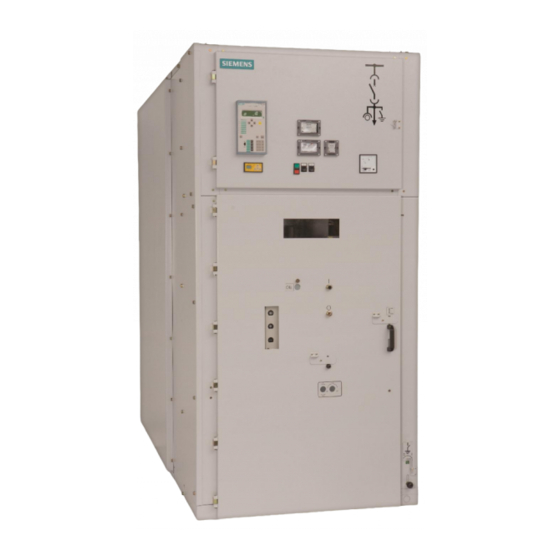
• Front doors and lateral switchgear end walls are powder-coated with resistant epoxy resin Material • Individual modular compartments in solid-wall design • Modular compartments bolted together 8BT2 truck-type circuit breaker switchgear is of the modular type and has four compartments. Wall standing type 8BT2 panel Free standing type 8BT2 panel Fig4. - Page 15 • For accommodation of protection, control, measuring and metering equipment • Plug-in bus wires and control cables • Standard version with 750 mm height • Door hinge on the left 881-4027.9 * INSTALLATION AND OPERATING INSTRUCTIONS 8BT2 * Revision 04...
-
Page 16: Basic Panel Types
1250 2000 2500 Natural Air forced with one fan 3150 Air forced with one fan Air forced with one fan Revision 04 * INSTALLATION AND OPERATING INSTRUCTIONS 8BT2 * 881-4027.9... - Page 17 After an internal arc fault Hot gas pressure due to an internal arc fault Red colored flag Air flow for natural ventilation Fig7. Working condition of the ventilation flap on high voltage compartment door 881-4027.9 * INSTALLATION AND OPERATING INSTRUCTIONS 8BT2 * Revision 04...
-
Page 18: Components
[V] min. [V] W [at DC] VA [at AC] 3AH3 type CB 3AH5 type CB 24 DC 48 DC 60 DC 110 DC 220 DC 110 AC 230 AC Revision 04 * INSTALLATION AND OPERATING INSTRUCTIONS 8BT2 * 881-4027.9... -
Page 19: Disconnector Truck
2.4.3. Metering truck Basic equipment of • Voltage transformers for all three phases metering truck Additional equipment for vacuum circuit • Electromagnetic interlocks breaker 881-4027.9 * INSTALLATION AND OPERATING INSTRUCTIONS 8BT2 * Revision 04... -
Page 20: Current & Voltage Transformer
Operating rod for closing / opening the circuit breaker mechanically Double bit key with a diameter of 3 mm for opening and closing the door of the low voltage compartment Revision 04 * INSTALLATION AND OPERATING INSTRUCTIONS 8BT2 * 881-4027.9... - Page 21 Hand crank for racking the switching device truck in and out Hand crank for manual charging of the circuit breaker’s closing spring in SERVICE position Lower shutter opening tool Operating lever for the withdrawable voltage transformers mechanism 881-4027.9 * INSTALLATION AND OPERATING INSTRUCTIONS 8BT2 * Revision 04...
- Page 22 • Phase comparison test units for capacitive voltage indicators type EPV-HR (e.g. Pfisterer, including 2HR-LRM adapters and storage bag) (fig9) Fig8. Test unit for capacitive interface and indicators Fig9. Test unit for phase comparison Revision 04 * INSTALLATION AND OPERATING INSTRUCTIONS 8BT2 * 881-4027.9...
-
Page 23: Dispatch And Storage
3.1. Delivery condition 8BT2 cubicles are factory assembled and the withdrawable parts are in the service position and the doors are closed during the dispatch. They are checked at the works for completeness in terms of the order and simultaneously subjected to routine test to IEC publication 62271-200, and are therefore tested for correct structure and function. - Page 24 In the individual case, the electronic components must be checked regarding the permissible limit temperatures and the relevant temperatures for the application (e.g. Siemens Siprotec in the range from -25 °C to +70 °C). • In a weatherproof place •...
-
Page 25: Installation Of The Switchgear
When the installation is in the scope of supply of the manufacturer, the regional SIEMENS representative requires the following information from you several weeks before the delivery of the switchgear. -
Page 26: Foundation
• If the foundation has to be resistant to earthquakes, additional points must be considered. Please ask your regional SIEMENS representative for the advice on this special condition. • Determine level differences between the installation surfaces of the panels using a measuring sheet, and compensate them with shims (0.5 to 1.0 mm). -
Page 27: Unloading Units
Attach ropes far enough on the hoisting tackle so that they cannot exert any forces on the cubicle walls under load. The hoisting tackle can optionally be ordered as an accessory (fig11). Do not drag the cubicle along the ground. 881-4027.9 * INSTALLATION AND OPERATING INSTRUCTIONS 8BT2 * Revision 04... -
Page 28: The Completeness And Transport Damage
Please ensure that the lifting gear used meets the requirements of the weight loads of the panels from the table (see page22, “Transport weights and dimensions with packing”) as a minimum. Revision 04 * INSTALLATION AND OPERATING INSTRUCTIONS 8BT2 * 881-4027.9... - Page 29 (fig15). Fig15. Transport unit on boards placed on roller pads Lift one side, then the other side of the transport unit and slowly lower it on the 881-4027.9 * INSTALLATION AND OPERATING INSTRUCTIONS 8BT2 * Revision 04...
-
Page 30: Assembly Of The Switchgear
(It depends on the switchgear condition determined by the customer). 4.3.1. Bolting panels together For perfect operation of 8BT2 switchgear it is necessary to align the individual panels and bolt them firmly together after erection. Screw’s tensile class should be 8.8. Tightening torques... - Page 31 Place the first panel at the right end. Mount four fixing tools (pos.nr. in fig17) at the four corners (pos.nr. in fig17). Fig17. Using the fixing tools to bolt panels together 881-4027.9 * INSTALLATION AND OPERATING INSTRUCTIONS 8BT2 * Revision 04...
-
Page 32: Fastening Panels To The Foundation
Floor fixing with dowels option Floor fixing types option Hammer head screw C profile CB 60-10 A-A section in floor drawings A-A section in floor drawings A-A section in floor drawings Revision 04 * INSTALLATION AND OPERATING INSTRUCTIONS 8BT2 * 881-4027.9... -
Page 33: Assembly Of The Busbars (Feeder And Coupling Panels)
Remove the fixing bolts of both pressure relief flaps (pos.nr. in fig18) over the pressure relief flaps busbar compartment The pressure relief flaps over the busbar compartment can be removed. 881-4027.9 * INSTALLATION AND OPERATING INSTRUCTIONS 8BT2 * Revision 04... - Page 34 Mount the strain washers so that the side cambered outwards points at the bolt head or the nut. NOTE! All bolts used in main busbar assembly are “mushroom head type”. Mushroom head bolt with nut Revision 04 * INSTALLATION AND OPERATING INSTRUCTIONS 8BT2 * 881-4027.9...
- Page 35 Fig19. Main busbar / Dropper bars ratings _ 800A / 800A Fig20. Main busbar / Dropper bars ratings _ 1250A / 800A 881-4027.9 * INSTALLATION AND OPERATING INSTRUCTIONS 8BT2 * Revision 04...
- Page 36 Fig21. Main busbar / Dropper bars ratings _ 1250A / 1250A Fig22. Main busbar / Dropper bars ratings _ 2000A / 800A Fig23. Main busbar / Dropper bars ratings _ 2000A / 1250A Revision 04 * INSTALLATION AND OPERATING INSTRUCTIONS 8BT2 * 881-4027.9...
- Page 37 Fig24. Main busbar / Dropper bars ratings _ 2000A / 2000A Fig25. Main busbar / Dropper bars ratings _ 2500A - 3150A / 800A Fig26. Main busbar / Dropper bars ratings _ 2500A - 3150A / 1250A 881-4027.9 * INSTALLATION AND OPERATING INSTRUCTIONS 8BT2 * Revision 04...
-
Page 38: Busbar Compartment Separation (Optional)
Fig27. Main busbar / Dropper bars ratings _ 2500A - 3150A / 2000A Fig28. Main busbar / Dropper bars ratings _ 2500A - 3150A / 2500 – 3150A 4.3.4. Busbar compartment separation (Optional) Insulated separation plate Revision 04 * INSTALLATION AND OPERATING INSTRUCTIONS 8BT2 * 881-4027.9... - Page 39 The threads of the bolts and nuts must be dry and non-greasy. Check contact surfaces of busbars, brush if necessary and apply a thin film of Shell Vaseline 8422 DAB 8. 881-4027.9 * INSTALLATION AND OPERATING INSTRUCTIONS 8BT2 * Revision 04...
- Page 40 3x80x10 3x80x10 M12x60 M12x50 M12x75 Please see the following drawings related to the connection details of lower main busbars for all current rating combinations in the sectionalizing and busriser panels: Revision 04 * INSTALLATION AND OPERATING INSTRUCTIONS 8BT2 * 881-4027.9...
- Page 41 Sectionalizing panel at the left hand side – Busriser panel at the right hand side Sectionalizing Busriser Fig29. 800A Assembly of Coupling bars 881-4027.9 * INSTALLATION AND OPERATING INSTRUCTIONS 8BT2 * Revision 04...
- Page 42 Fig30. 1250A Assembly of Coupling bars Revision 04 * INSTALLATION AND OPERATING INSTRUCTIONS 8BT2 * 881-4027.9...
- Page 43 Fig31. 2000A Assembly of Coupling bars 881-4027.9 * INSTALLATION AND OPERATING INSTRUCTIONS 8BT2 * Revision 04...
- Page 44 When locations of Sectionalizing and Busriser panels are reversed, the assembly of lower main busbar is also reversed. Please see the below sample for 2500A – 3150A rating assembly (the same method is available for other ratings, 800A, 1250A, 2000A): Busriser Sectionalizing Revision 04 * INSTALLATION AND OPERATING INSTRUCTIONS 8BT2 * 881-4027.9...
-
Page 45: Earthing
Each panel has a fixed earthing bar in the cable compartment. The intermediate copper bridge to interconnect two adjacent panels is a part of the accessories. Get the intermediate copper bridge from the accessory box. 881-4027.9 * INSTALLATION AND OPERATING INSTRUCTIONS 8BT2 * Revision 04... -
Page 46: 4.3.5.2. Earthing The Switchgear
Do not stay under a lifted compartment! Lift low voltage compartment up to height of upper edge of high voltage door with suitable lifting equipment. Fig35. Lifting and positioning the low-voltage compartment Revision 04 * INSTALLATION AND OPERATING INSTRUCTIONS 8BT2 * 881-4027.9... -
Page 47: Assembly Of The Arc Routing Plates
Position the panel on its final place of installation. Proceed in the same way with the adjacent panel. Interconnect both arc routing plates before positioning the next panel. 881-4027.9 * INSTALLATION AND OPERATING INSTRUCTIONS 8BT2 * Revision 04... -
Page 48: Gas Pressure Relief From The Ear
Fig39. Final assembly of the arc routing plates at the wall standing switchgear version Revision 04 * INSTALLATION AND OPERATING INSTRUCTIONS 8BT2 * 881-4027.9... -
Page 49: Gas Pressure Relief From The Top
To be able to apply arc routing plates efficiently, the above min. distances should be considered. Fig41. Assembly of arc routing plates Fig42. Final assembly of the arc routing plates at the free standing switchgear version, 25kA 881-4027.9 * INSTALLATION AND OPERATING INSTRUCTIONS 8BT2 * Revision 04... - Page 50 To be able to apply arc routing plates efficiently, the above min. distances should be considered. Fig44. Assembly of arc routing plates Fig45. Final assembly of the arc routing plates at the free standing switchgear version, 31.5kA Revision 04 * INSTALLATION AND OPERATING INSTRUCTIONS 8BT2 * 881-4027.9...
-
Page 51: Assembly Of The Closed Relief Duct
Interconnect both pressure relief duct before positioning the next panel. NOTE! For all connections, the bolt type (M8x25) is used. Hexagon head bolts with set-nuts which are already pressed on steel parts at the factory. 881-4027.9 * INSTALLATION AND OPERATING INSTRUCTIONS 8BT2 * Revision 04... - Page 52 Assembly of the closed pressure relief duct with lateral exit Fig47. Assembly of the closed pressure relief duct Pos.nr. in fig47: Endplate. It is assembled on the right or left end panel. Revision 04 * INSTALLATION AND OPERATING INSTRUCTIONS 8BT2 * 881-4027.9...
- Page 53 ) is more than one (fig48). The connection details of the frame (pos.nr. ) to the wall outlet are shown in fig49. “Z-detail” “Z-detail” Pressure relief flaps Fig49. Wall opening details for lateral exit 881-4027.9 * INSTALLATION AND OPERATING INSTRUCTIONS 8BT2 * Revision 04...
- Page 54 Exhaust channel (rear exit) Fig50. Closed pressure relief duct with rear exit Assembly of the closed pressure relief duct with rear exit Fig51. Assembly of the closed pressure relief duct Revision 04 * INSTALLATION AND OPERATING INSTRUCTIONS 8BT2 * 881-4027.9...
- Page 55 ) is more than one. The connection details of the frame (pos.nr. ) to the wall outlet are as below: “Z-detail” “Z-detail” Pressure relief flaps Fig53. Wall opening details for lateral exit 881-4027.9 * INSTALLATION AND OPERATING INSTRUCTIONS 8BT2 * Revision 04...
-
Page 56: Electrical Connections
• Earthing switch closed, seem Page 78 – clause 6.10, "Operating the feeder earthing switch" • Truck removed from the panel, see Page 71 – clause 6.6, “Racking the switching device Revision 04 * INSTALLATION AND OPERATING INSTRUCTIONS 8BT2 * 881-4027.9... - Page 57 491mm. If longer one needs to be used, please consult SIEMENS for the special design of deep bottom pan. The solution will be to adapt the deep bottom pan as explained in clause 4.3.9.1.3. (page62). Dimensions of deep bottom pan can be changed according to the cable termination length and diameter.
-
Page 58: Front Access Of The Panel
Step4………………… Unscrew the lower shutter arm. (fig59) Right side is prepared Perform steps 1, 2, 3, 4 on lower shutter drive lever and lower shutter analogously for the left side. Revision 04 * INSTALLATION AND OPERATING INSTRUCTIONS 8BT2 * 881-4027.9... - Page 59 Push the knob into left position and hold. Insert the lower shutter opening tool at the left side by meeting the two slots in the lower shutter arm with the lugs (fig63 and 64). 881-4027.9 * INSTALLATION AND OPERATING INSTRUCTIONS 8BT2 * Revision 04...
- Page 60 • Lower shutter opening tool inserted and locked. Procedure Push the lower shutter opening tool at the two handles inside the panel until the lower shutter is fully open (fig65 – 67). Revision 04 * INSTALLATION AND OPERATING INSTRUCTIONS 8BT2 * 881-4027.9...
-
Page 61: Rear Access Of The Panel
Do not touch live components. Ensure that the switchgear is only operated by qualified personnel who are familiar with the operating instructions and observe the warnings. Observe the five safety rules. 881-4027.9 * INSTALLATION AND OPERATING INSTRUCTIONS 8BT2 * Revision 04... - Page 62 The rear cover cannot be removed unless the withdrawable voltage transformers are the rear cover disconnected. Fig71. View of the rear cover Move two operating levers (pos.nr. in fig71) at the same time as shown in fig72. Revision 04 * INSTALLATION AND OPERATING INSTRUCTIONS 8BT2 * 881-4027.9...
- Page 63 Use only cable terminations with the dimensions hereafter. Depending on the manufacturer of the cable terminations, the dimensions may differ from those described in here. Please make sure that dimensions do not exceed the limit values. 881-4027.9 * INSTALLATION AND OPERATING INSTRUCTIONS 8BT2 * Revision 04...
-
Page 64: Deep Bottom Pans (Optional)
This is not a standard application. Deep bottom pan is available as supplementary equipment for the switchgear. Fig76. Side view of deep bottom pan with standard dimensions Revision 04 * INSTALLATION AND OPERATING INSTRUCTIONS 8BT2 * 881-4027.9... -
Page 65: 4.3.9.2. Control Cable Connection
Interconnection wiring between the switchgear and the other location The control cables coming from outside to the switchgear are put into the channel. The following drawings mention the foundation detail and the channel inside of the panel. 881-4027.9 * INSTALLATION AND OPERATING INSTRUCTIONS 8BT2 * Revision 04... -
Page 66: 4.3.9.3. Bus Wire Connection
Please be aware of the below table regarding to the torque values during the control process. The bolted copper joints Control tightening 60 Nm with strain washer torque 145 Nm 6.8 Nm 17 Nm 35 Nm The bolted steel joints Control tightening Revision 04 * INSTALLATION AND OPERATING INSTRUCTIONS 8BT2 * 881-4027.9... -
Page 67: Checking High Voltage Connections
• Paint pen for minor paint damages • Touch-up paint, 1 kg tin 4.4.6. Checking installation work Check whether all installation work has been performed properly in accordance with the previous sections of installation. 881-4027.9 * INSTALLATION AND OPERATING INSTRUCTIONS 8BT2 * Revision 04... -
Page 68: Commissioning
• Earthing and short-circuiting facility (optional) • Voltage tester or detecting system (optional) • Lower shutter opening tool (optional) Ensure that the installation work has been performed properly. Ensure that all covers have been fitted. Revision 04 * INSTALLATION AND OPERATING INSTRUCTIONS 8BT2 * 881-4027.9... -
Page 69: 5.2.4. Checking Interlocks Mechanically
In this case, make the following preparations: Remove voltage transformers as well as surge arresters and surge limiters. Protect bushings of transformers, surge arresters and surge limiters in a surge-proof way using suitable sealing caps. 881-4027.9 * INSTALLATION AND OPERATING INSTRUCTIONS 8BT2 * Revision 04... -
Page 70: Putting Into Service
When all the incoming feeders have been connected: outgoing consumer feeders One after the other, switch on all outgoing feeders with connected consumers. Now, all feeders are energized; the switchgear is totally in operation. Revision 04 * INSTALLATION AND OPERATING INSTRUCTIONS 8BT2 * 881-4027.9... -
Page 71: Customer Support
If the fault persists, contact our SIEMENS Customer Support Center. Repairs Repairs are carried out by fully trained Siemens engineers, who arrive equipped with original spare parts for your switchgear. Before you call To help us deal with your query more quickly, make sure you have the following information at hand: •... -
Page 72: Operation Of The Switchgear
The perfect and safe operation of this switchgear is conditional on correct erection and installation according to the installation instructions. 6.2. Control elements and indicators Fig81. Control elements, circuit-breaker panel Revision 04 * INSTALLATION AND OPERATING INSTRUCTIONS 8BT2 * 881-4027.9... -
Page 73: Access To Compartments
CHARGED 6.3. Access to compartments Regarding accessibility to the individual compartments, 8BT2 switchgear fulfills the loss of service continuity category LSC 2B according to IEC 62271-200. The degree of protection of the individual compartments between each other is IP2X. The type of accessibility is provided as follows:... -
Page 74: Opening And Closing The High Voltage Compartment Door
Pull the door handle upwards and open the door Pull the door handle upwards and close the door Push the door handle downwards Close step step door Result High-voltage door is open. High-voltage door is closed. Revision 04 * INSTALLATION AND OPERATING INSTRUCTIONS 8BT2 * 881-4027.9... -
Page 75: Moving The Withdrawable Device Truck Into And Out Of Panel
Push the switching device truck into the panel as far as it will go. Fold the locking gates of the guide rails to the outside. Turn the lateral fixing levers 90° inside. 881-4027.9 * INSTALLATION AND OPERATING INSTRUCTIONS 8BT2 * Revision 04... -
Page 76: Low Voltage Plug Connection And Coding
(Please see fig83 for the connection). Revision 04 * INSTALLATION AND OPERATING INSTRUCTIONS 8BT2 * 881-4027.9... - Page 77 Fig85. View of the socket on the circuit breaker Pin-socket Pin-socket Fig86. View of different coded sockets The pin-socket combination can let the right circuit breaker put into the related panel. So, 881-4027.9 * INSTALLATION AND OPERATING INSTRUCTIONS 8BT2 * Revision 04...
-
Page 78: Racking The Withdrawable Device Truck
(pos.nr. in fig87) turn 90º clockwise to the “Racking free” position and turn 90° counter-clockwise to the "Racking free" (manual racking). position (manual racking). Revision 04 * INSTALLATION AND OPERATING INSTRUCTIONS 8BT2 * 881-4027.9... - Page 79 Remove the double-bit key. Remove the double-bit key. Result The switching device truck was racked from TEST The switching device truck was racked from to SERVICE position. SERVICE to TEST position. 881-4027.9 * INSTALLATION AND OPERATING INSTRUCTIONS 8BT2 * Revision 04...
-
Page 80: Operating The Circuit Breaker
The position indicator changes from "0" position The position indicator changes from "I" position to to "I" position. "0" position. The operation counter is increased by 1. The circuit-breaker is open. The circuit-breaker is closed. Revision 04 * INSTALLATION AND OPERATING INSTRUCTIONS 8BT2 * 881-4027.9... - Page 81 Turn hand crank clockwise approx. 25 turns until the "spring charged" indication appears in the inspection window. Remove hand crank. The spring is latched automatically. The energy required for the operating sequence OPEN-CLOSED-OPEN (auto reclosing) is stored in the spring. 881-4027.9 * INSTALLATION AND OPERATING INSTRUCTIONS 8BT2 * Revision 04...
-
Page 82: Operating The Feeder And Busbar Earthing Switches
Insert the operating lever for the feeder earthing switch into the opening. switch into the opening. Turn the operating lever clockwise approx. 90° into Turn the operating lever counter-clockwise CLOSED position. approx. 90° into OPEN position. Revision 04 * INSTALLATION AND OPERATING INSTRUCTIONS 8BT2 * 881-4027.9... -
Page 83: Operation Of The Fused Voltage Transformers In The Cable Compartment
Tripped fuses can cause hidden damages on the other fuses. It is highly recommended to replace all fuse-links, even if only one fuse has tripped. The fuses can be replaced while the cable compartment is energized. 881-4027.9 * INSTALLATION AND OPERATING INSTRUCTIONS 8BT2 * Revision 04... - Page 84 Check by looking through inspection window (pos.nr in fig91) that inner shutter is closed. Remove the rear cover by means of the handles (fig93). Fig93. Removing the rear cover Revision 04 * INSTALLATION AND OPERATING INSTRUCTIONS 8BT2 * 881-4027.9...
- Page 85 Fig95. Replacement of the voltage transformer fuse Insert the new fuse-link into the holder with the striker at the top. Mount the cap of the fuse holder. The fuse replacement is completed. 881-4027.9 * INSTALLATION AND OPERATING INSTRUCTIONS 8BT2 * Revision 04...
-
Page 86: Verification Of Safe Isolation From Supply (Lrm System)
The perfect function of the coupling section must have been verified according to: • IEC 78/183/CDV Plug voltage indicator in all three phases L1, L2, L3 of the interface. Fig97: VOIS+: Cover closed Revision 04 * INSTALLATION AND OPERATING INSTRUCTIONS 8BT2 * 881-4027.9... -
Page 87: Verification Safe Isolation (W/O Lrm System)
• Switching device truck out of panel • Earthing accessories available The earthing and short-circuiting facility is connected to the earthing point at the front of the panel with an M12 bolt. 881-4027.9 * INSTALLATION AND OPERATING INSTRUCTIONS 8BT2 * Revision 04... - Page 88 Connect the earthing and short-circuiting facility to the earthing point.. Open the busbar shutters by pushing the levers. Connect the contacts of the earthing and short-circuiting facility to the upper contacts of the panel and screw tight. Revision 04 * INSTALLATION AND OPERATING INSTRUCTIONS 8BT2 * 881-4027.9...
-
Page 89: Maintenance And Service
If there is any visible erosion, the stressed components must be replaced. To do this, please contact the regional SIEMENS representative. -
Page 90: Maintenance Of Vacuum Circuit Breaker
Spare parts may only be replaced by instructed and certified personnel in order to guarantee perfect operation of the switchgear. The manufacturer’s product liability is not effective if at least one of the following criteria applies: Revision 04 * INSTALLATION AND OPERATING INSTRUCTIONS 8BT2 * 881-4027.9... -
Page 91: Service Information
Replacement of Panels can be replaced after undoing the panel connecting bolts. switchpanels If you are planning to replace a panel, please contact your regional SIEMENS representative, as the replacement must only be done by experts with special tools. Replacement of... -
Page 92: Trouble Shooting
• Lubricants • Bolts, washers, nuts, rivets As delivered by Siemens, the switchgear does not contain hazardous materials as per the Hazardous Material Regulations applicable in the Federal Republic of Germany. In other countries, the locally applicable laws and regulations must be followed. -
Page 93: Index
Fixing on wooden panels for delivery ......15 Fixing points..............18 Components..............60 Flexibility ..............55 Consumer feeders, connecting ........54 Floor fixing points ............18 Control cable connections..........49 Floor openings ............. 18 881-4027.9 * INSTALLATION AND OPERATING INSTRUCTIONS 8BT2 * Revision 04... - Page 94 Re-availability ............... 55 Measuring sheet, foundation........17 Replacement of switchpanels and components ..74 Metering panel, description......... 59 Metering truck ............. 61 Safe isolation from supply, verfication without LRM ... 99 Revision 04 * INSTALLATION AND OPERATING INSTRUCTIONS 8BT2 * 881-4027.9...
- Page 95 Switching device truck, racking ........82 Wooden pallets, removing the switchgear from ..15 Switching device truck, racking positions..... 82 Switching device truck, racking to SERVICE position ... 82 X-ray regulations............69 881-4027.9 * INSTALLATION AND OPERATING INSTRUCTIONS 8BT2 * Revision 04...
- Page 96 Imprint Siemens AG Energy Sector Division Power Distribution Schaltanlagenwerk Frankfurt Carl-Benz-Str. 22 D-60386 Frankfurt © Siemens AG 2010 881-4027.9 * INSTALLATION AND OPERATING INSTRUCTIONS 8BT2 * Revision 04...
Need help?
Do you have a question about the 8BT2 and is the answer not in the manual?
Questions and answers