Table of Contents
Advertisement
Quick Links
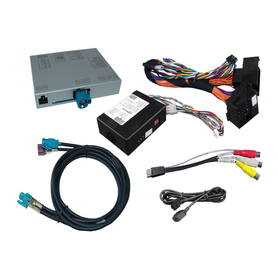
Compatible with Citroen and Peugeot vehicles
with SMEG or SMEG+ infotainment system
with 4pin HSD connector on the monitor
Product features
Video-inserter for factory-infotainment systems
2 CVBS video-inputs for after-market devices (e.g. DVD-Player, DVB-T tuner)
CVBS Rear-view camera video-input
Automatic switching to rear-view camera input on engagement of reverse gear
Activatable parking guide lines for rear-view camera (not available for all vehicles)
Video-in-motion (ONLY for connected video-sources)
Video inputs PAL/NTSC compatible
Version 31.10.2018
r.LiNK Video-inserter
RL2-PC-HSD
Video-inserter for rear-view camera
and two additional video sources
HW CAM(V31)/A4L-HD(V35)
RL2-PC-HSD
Advertisement
Table of Contents

Related Manuals for NavLinkz r.LiNK RL2-PC-HSD


Summary of Contents for NavLinkz r.LiNK RL2-PC-HSD
- Page 1 r.LiNK Video-inserter RL2-PC-HSD Compatible with Citroen and Peugeot vehicles with SMEG or SMEG+ infotainment system with 4pin HSD connector on the monitor Video-inserter for rear-view camera and two additional video sources Product features Video-inserter for factory-infotainment systems 2 CVBS video-inputs for after-market devices (e.g. DVD-Player, DVB-T tuner) ...
-
Page 2: Table Of Contents
Contents Prior to installation 1.1. … Delivery contents 1.2. Checking the compatibility of vehicle and accessories 1.3. Boxes and connectors 1.3.1. CAN-bus box 1.3.2. Video-interface 1.4. Dip-switch settings 1.4.1. 8 dip - black 1.4.1.1. …Enabling the interface’s video inputs (dip 2-3) 1.4.1.2. -
Page 3: Prior To Installation
Legal Information By law, watching moving pictures while driving is prohibited, the driver must not be distracted. We do not accept any liability for material damage or personal injury resulting, directly or indirectly, from installation or operation of this product. This product should only be used while standing or to display fixed menus or rear-view-camera video when the vehicle is moving, for example the MP3 menu for DVD upgrades. -
Page 4: Checking The Compatibility Of Vehicle And Accessories
1.2. Checking the compatibility of vehicle and accessories Voraussetzungen Brand Model Navigation Berlingo since model year 2015 C4 since model year 2015 C4 Cactus since model year 2014 SMEG/SMEG+/DS Connect Citroen C4 Picasso model year 2014-2016 Nav Touch Navigation DS3 since model year 2016 DS4 since model year 2015- 208 model year up to about 2016 2008 model year up to about 2016... -
Page 5: Video-Interface
1.3.2. Video-interface The video-interface converts the video signals of connected after-market sources in a factory monitor compatible picture signal which is inserted in the factory monitor, by using separate trigger options. Further it reads the vehicle’s digital signals out of the vehicle’s CAN-bus and converts them for the video interface. -
Page 6: Rear-View Camera Setting (Dip 5)
1.4.1.1. Enabling the interface’s video inputs (dip 1-3) Only the enabled video inputs can be accessed when switching through the interface’s video sources. It is recommended to enable only the required inputs for the disabled will be skipped when switching through the video interfaces inputs. 1.4.1.2. -
Page 7: Connection Schema
2.2. Connection scheme Version 31.10.2018 HW CAM(V31)/A4L-HD(V35) RL2-PC-HSD... -
Page 8: Connection - Video-Interface And Can-Box
2.3. Connection - video-interface and CAN-box The CAN-bus box reads digital signals from the CAN-bus and converts them for the video- interface. ACC +12V max. 0.5A (red of 6pin) and reverse gear +12V max. 0.5A (green of 6pin) constant signal. Video-source switching (white of 6pin) as +12V impulse. Connect theblack female 10pin connector of the Quadlock harness to the male 10pin connector of the CAN-box. -
Page 9: Connection - Factory Monitor
2.4. Connection - factory monitor Remove factory monitor. Remove the white female 4pin HSD connector from the rearside of the factory monitor and connect it to the aubergine colored male 4pin HSD connector of the picture signal cable. Connect the waterblue colored female 4pin HSD connector of the picture signal cable to the white male 4pin HSD connector of the factory monitor. -
Page 10: Connection - Head-Unit
2.5. Connection - head-unit Remove head-unit. Remove the female Quadlock connector of the vehicle harness from the rearside of the head unit and connect it to the male Quadlock connector of the Quadlock harness. Connect the opposite female Quadlock connector of Quadlock harness to the previously become free male Quadlock connector of the head-unit. -
Page 11: Connecting - Video Sources
2.6. Connection – video sources It is possible to connect 2 after-market Video-sources and 1 after-market rear-view camera to the video-interface. Before final installation of the peripheral devices, we recommend a test-run of the interface. Due to changes in the production of the vehicle manufacturer is always the possibility of incompatibility. -
Page 12: Audio-Insertion
2.6.1. Audio insertion This interface can only insert video signals into the factory infotainment. Audio insertion must be done by factory audio AUX input or FM-modulator. The inserted video-signal can be activated simultaneously to each audio-mode of the factory infotainment. If 2 AV sources shall be connected to the infotainment, additional electronic is necessary to switch the audio signals. -
Page 13: Case 2: Can-Box Does Not Detect Reverse Gear
2.6.2.2. Case 2: CAN-box does not detect reverse gear If the CAN-bus interface does not deliver +12V on the green wire of the 6pin to 8pin cable when reverse gear is engaged (not all vehicles are compatible) an external switching signal from the reverse gear light is required. -
Page 14: Connection Video-Interface And Keypad
2.7. Connecting video-interface and keypad Connect the female 4pin connector of the keypad to the male 4pin connector of the video-interface. Version 31.10.2018 HW CAM(V31)/A4L-HD(V35) RL2-PC-HSD... -
Page 15: Picture Settings And Guide Lines
2.8. Picture settings and guide lines The picture settings are adjusted by the 3 buttons on the video-interface. Press the MENU button to open the OSD settings menu or to switch to the next menu item. Press UP and DOWN will change the selected value. The buttons are embedded in the housing to avoid accidental changes during or after installation. -
Page 16: Interface Operation
Interface operation 3.1. By LIST-key The LIST-key on the steering wheel is used to switch among all the inputs. The order is: Factory video video AV1 video AV2 factory video … Inputs which are not enabled are skipped. Switchover by vehicle buttons isn’t possible in all vehicles. - Page 17 FAQ – Trouble shooting Interface functions For any troubles which may occur, check the following table for a solution before requesting support from your vendor. Symptom Reason Possible solution Not all connectors have been reconnected to factory head- Connect missing connectors. unit or monitor after installation.
-
Page 18: Technical Support
6pin to 8pin cable and isolate both ends. Technical Support Please note that direct technical support is only available for products purchased directly from NavLinkz GmbH. For products bought from other sources, contact your vendor for technical support. NavLinkz GmbH...
Need help?
Do you have a question about the r.LiNK RL2-PC-HSD and is the answer not in the manual?
Questions and answers