Table of Contents
Advertisement
Quick Links
Video inserter
RL4-SY4
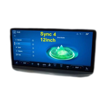
Compatible with
Ford
vehicles with Sync 4 infotainment
with 12inch or 13,2inch monitor
Video-inserter for front- and rear-view camera
and two more video inputs
Product features
• Video-inserter for factory-infotainment systems
• 1 CVBS Input for rear-view camera
• 1 CVBS Input for front camera
• 2 CVBS Video-inputs for after-market Video sources (e.g. USB-Player, DVB-T Tuner)
• Automatic switching to rear-view camera input on engagement of the reverse gear
• Automatic front camera switching after reverse gear for 10 seconds
• Activatable parking guide lines for rear-view camera (not available for all vehicles)
• Activatable PDC (not available for all vehicles)
• Video-in-motion (ONLY for connected video-sources)
• Video-inputs NTSC compatible
Version 22.02.2023
HW: CAM(V100) / V11)
RL4-SY4
Advertisement
Table of Contents

Subscribe to Our Youtube Channel
Related Manuals for NavLinkz RL4-SY4


Summary of Contents for NavLinkz RL4-SY4
- Page 1 Video inserter RL4-SY4 Compatible with Ford vehicles with Sync 4 infotainment with 12inch or 13,2inch monitor Video-inserter for front- and rear-view camera and two more video inputs Product features • Video-inserter for factory-infotainment systems • 1 CVBS Input for rear-view camera •...
-
Page 2: Table Of Contents
Case 2Interface does not receive the reverse gear signal 2.6. Connection - video-interface and external keypad 2.7. Picture settings 3. Interface operation 4. Specifications 5. FAQ – Trouble Shooting-Interface functions 6. Technical support Version 22.02.2023 HW: CAM(V100) / V11) RL4-SY4... -
Page 3: Prior To Installation
Due to changes in the production of the vehicle manufacturer there’s always a possibility of incompatibility. 1.1. Delivery contents Take down the serial number of the interface and store this manual for support purposes: ____________________ Version 22.02.2023 HW: CAM(V100) / V11) RL4-SY4... -
Page 4: Checking The Compatibility Of Vehicle And Accessories
A manually front camera switching is possible by external keypad. Abstandslinien und PDC Displayed dynamic guidelines and optical PDC are not available in all vehicles Video input signal Only NTSC video sources compatible. Version 22.02.2023 HW: CAM(V100) / V11) RL4-SY4... -
Page 5: Boxes And Connectors - Video Interface
Further it reads the vehicle’s digital signals out of the vehicle’s CAN-bus and converts them for the video interface. Version 22.02.2023 HW: CAM(V100) / V11) RL4-SY4... -
Page 6: Settings - 8 Dip Switches (Black)
*The front camera will automatically be switched for 10 seconds after disengaging the reverse gear. See the following chapters for detailed information. After each Dip-switch-change a power-reset of the Video interface has to be performed! Version 22.02.2023 HW: CAM(V100) / V11) RL4-SY4... -
Page 7: Activating The Front Camera (Dip 1)
PDC cannot be used. Note: Dip 4 and dip8 are out of function and have to be set to OFF! After each Dip-switch-change a power-reset of the Video Interface has to be performed! Version 22.02.2023 HW: CAM(V100) / V11) RL4-SY4... -
Page 8: Settings - 2 Dip Switches (Selection Head-Unit - Black)
Before the final installation, we recommend a test-run of the interface. Due to changes in the production of the vehicle manufacturer, there’s always the possibility of incompatibility. 2.1. Place of connection The video interface has to be connected at the vehicle`s head-unit. Version 22.02.2023 HW: CAM(V100) / V11) RL4-SY4... -
Page 9: Connection Schema
2.2. Connection schema Version 22.02.2023 HW: CAM(V100) / V11) RL4-SY4... -
Page 10: Connection - Factory Head Unit
Note: Depending on the installation conditions, the enclosed picture signal cable may also be mounted upside down, concerning it’s HSD connectors . However, it‘s connection must only be made at the head unit! Version 22.02.2023 HW: CAM(V100) / V11) RL4-SY4... - Page 11 54pin connector of 10pin power/CAN cable. Connect the opposing female 54pin locking-connector of the 10pin Power/CAN cable to the previously become free male 54pin connector at the rear-side of the head-unit.-. Version 22.02.2023 HW: CAM(V100) / V11) RL4-SY4...
-
Page 12: Analogue Power Supply
If, after connecting the PNP harness, no interface LED lightens up while the ignition is turned on, the purple coloured wire Manual ACC of the 12pin interface cable has to be connected additionately to S-contact terminal 86s +12V (e.g. glove compartment illumination). Version 22.02.2023 HW: CAM(V100) / V11) RL4-SY4... -
Page 13: Power Supply Output For Front Cam
+12V (max. 3A) when reverse gear is engaged incl. 10 seconds delay after reverse gear is disengaged and +12V by manual switching to front camera by keypad (short press) Dip 1 OFF +12V ACC Version 22.02.2023 HW: CAM(V100) / V11) RL4-SY4... -
Page 14: Connection - Video-Sources
Connect the front camera’s video RCA connector to the 12pin interface cable’s female RCA connector „Front V3“. Connect the video RCA of the AV source 1 and 2 to the 12pin interface cable’s female RCA connector “Left (V1)” ”Right (V2)”. Version 22.02.2023 HW: CAM(V100) / V11) RL4-SY4... -
Page 15: Audio Insertion
(short press) from any image mode. The power supply output gives +12V then, as well (if Dip 1 is set to ON and the front camera input is selected). Attention: A long press of the external keypad push button will switch the interface to the next source. Version 22.02.2023 HW: CAM(V100) / V11) RL4-SY4... -
Page 16: After-Market Rear-View Camera
“Camera IN” while the reverse gear is engaged. Additionally, the +12V (max. 3A) power supply for the rear-view camera can be taken from the green wire of the 12pin interface cable. Version 22.02.2023 HW: CAM(V100) / V11) RL4-SY4... -
Page 17: Case 2Interface Does Not Receive The Reverse Gear Signal
Connect the output connector (87) of the relay to the rear-view camera’s power- cable, like you did it to the green “Reverse-IN” cable before. Connect stabile and permanent +12V to the relay’s input connector (30). Version 22.02.2023 HW: CAM(V100) / V11) RL4-SY4... -
Page 18: Connection - Video-Interface And External Keypad
Connect the female 4pin connector of the keypad to the male 4pin connector of the 12pin interface cable. Note: Even if switching through several video sources by the keypad mightn’t be required, the invisible connection and availability is strongly recommended. Version 22.02.2023 HW: CAM(V100) / V11) RL4-SY4... -
Page 19: Picture Settings
Note: The OSD menu is only shown when a working video source is connected to the selected video-input of the interface. The following settings are available: Contrast Brightness Saturation Position H = horizontal picture position Position V = vertical picture position Version 22.02.2023 HW: CAM(V100) / V11) RL4-SY4... -
Page 20: Interface Operation
Stand-by power drain Power 250mA @12V Video input 0.7V - 1V Video input formats NTSC Temperature range -40°C to +85°C Dimensions video-box 117 x 25 x 103 mm (W x H x D) Version 22.02.2023 HW: CAM(V100) / V11) RL4-SY4... -
Page 21: Faq - Trouble Shooting-Interface Functions
Test camera under natural light outside the garage. flickers. directly into the camera. Camera input picture is Protection sticker not Remove protection sticker from lens. bluish. removed from camera lens. Version 22.02.2023 HW: CAM(V100) / V11) RL4-SY4... -
Page 22: Technical Support
6pin to 8pin cable and isolate both ends. Technical Support Please note that direct technical support is only available for products purchased directly from NavLinkz GmbH. For products bought from other sources, contact your vendor for technical support. NavLinkz GmbH...
Need help?
Do you have a question about the RL4-SY4 and is the answer not in the manual?
Questions and answers