
Subscribe to Our Youtube Channel
Related Manuals for V2 ZORUS


Summary of Contents for V2 ZORUS
- Page 1 ZIS510 IL 341-1 EDIZ. 12/12/2019 ZORUS IRREVERSIBLE ELECTROMECHANICAL PIVOTING ARM ACTUATOR FOR SWING GATES...
-
Page 3: Table Of Contents
INDEX 1 - GENERAL SAFETY INFORMATION ........................1.1 - TECHNICAL ASSISTANCE SERVICE ........................1.2 - PRELIMINARY CHECKS and IDENTIFICATION OF THE TYPE TO BE USED ............1.3 - EU DECLARATION OF CONFORMITY ....................... 2 - TECHNICAL DATA ..............................USE LIMITATIONS ..............................3 - INSTALLATION OF THE MOTOR .......................... -
Page 4: General Safety Information
V2 customer assistance service. 1 - GENERAL SAFETY INFORMATION • V2 declines all responsibility for failure to comply with good construction practice standards in addition to structural deformation of the gate that might occur during use. -
Page 5: Preliminary Checks And Identification Of The Type To Be Used
1.2 - PRELIMINARY CHECKS AND IDENTIFICATION OF THE TYPE TO BE USED The automation device should not be used until installation, as specified in “Testing and start-up”, has been performed. It should be remembered that the device does not compensate for defects caused by improper installation, or poor maintenance, thus, prior to proceeding with installation, ensure that the structure is suitable and meets current standards and, if necessary, perform any structural modifications aimed at the implementation of safety gaps and the protection or segregation of all crushing, shearing and transit zones, and verify that:... -
Page 6: Eu Declaration Of Conformity
Electromagnetic Compatibility Directive 2014/30/EU 2014/30/UE (EMC); 2006/42/CE (MD) ANNEX II, PART B Directive ROHS3 2015/863/EU The manufacturer V2 S.p.A., headquarters in Corso Principi di The relevant technical documentation is available at the national Piemonte 65, 12035, Racconigi (CN), Italy authorities’ request after justifiable request to: V2 S.p.A. -
Page 7: Installation Of The Motor
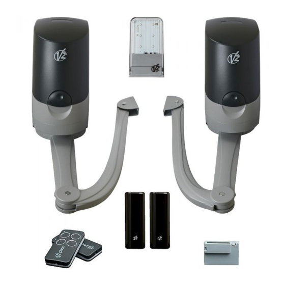
3 - INSTALLATION OF THE MOTOR 3.1 - INSTALLATION LAYOUT COMPONENTS ADDITIONAL ACCESSORIES Motor Key switch Transmitter Pillar photocells Receiving module Pillar-mounted digital radio switch Photocells Safety edges Flashing light ECO-LOGIC LENGTH OF THE CABLE < 10 metres from 10 to 20 metres from 20 to 30 metres Power supply 230V 3G x 1,5 mm... -
Page 8: Installation Of The Rear Fixing Bracket
3.2 - INSTALLATION OF THE REAR FIXING Measure value “C”, then trace a straight horizontal line in chart 1 against the obtained valued. Select BRACKET a point in the line, taking into account the desired opening angle, suitable for the column. Calculate the rear bracket position using chart. -
Page 9: Securing The Gear Motor To The Fixing Brackets
3.3 - SECURING THE GEAR MOTOR TO THE Secure the gear motor to the front bracket: FIXING BRACKETS Secure the gear motor arm to the bracket using the pin and seger supplied Secure the gear motor to the rear bracket: Secure the gear motor to the bracket using the screws, washers and nuts supplied Tighten the seger fully onto the pin seat... -
Page 10: Installation And Adjustment Of The Motor Limit Switches
3.5 - INSTALLATION AND ADJUSTMENT OF Fix the limit switches on the motor arm; these must also be installed in the presence of mechanical stops on the ground THE MOTOR LIMIT SWITCHES Release the gear motor Opening Closing 5. At this point re-install the arm onto the motor Remove the 2 screws underneath the motor and remove the cover Unscrew the screw in the motor arm and remove it... -
Page 11: Electrical Connections
3.6 - ELECTRICAL CONNECTIONS By screwing or unscrewing the two screws (A) on the motor, the two limit switches can be adjusted; then, using the two screws (B) block the two adjusting screws WARNING! • An incorrect connection can cause faults or dangerous situations;... -
Page 12: Control Unit
4 - CONTROL UNIT 4.2 - INSTALLATION PD12 is provided with a display that, not only makes Installation of control unit and safety devices must be carried out programming simple, but also allows a continuous monitoring of with power disconnected. the input statuses;... -
Page 13: External Photocell Connection
PHOTOCELLS - INSTRUCTIONS SAFETY RIBBONS - INSTRUCTIONS • If several edges, with normally closed contacts, are used, the • The control unit powers the photocells at a nominal voltage outputs should be connected in series. of 24 Vdc, with an electronic fuse that breaks the current in •... -
Page 14: Activation Inputs
4.7 - ACTIVATION INPUTS 4.8 - STOP For a better safety, you can fit a stop switch that will cause the (START and START P.) immediate gate stop when activated. This switch must have a normally close contact (NC) that will get open in case of PD12 control unit is equipped with two activation inputs, whose operation. -
Page 15: Lock
The ADI (Additional Devices Interface) interface of the control unit PD12 allows the connection to V2 optional modules. Refer to V2 catalogue or to the technical sheets to see which optional modules with ADI interface are available for this control unit. -
Page 16: Electrical Connection Summary
4.17 - ELECTRICAL CONNECTION SUMMARY Fuse: T1.6A Phase power supply 230Vac Earth Neutral power supply 230Vac Max 500mA BATTERY 24Vdc RECEIVER Control unit model: PD12 24Vdc 24 Vdc POWER SUPPLY - 48 -... -
Page 17: Control Panel
5 - CONTROL PANEL B1 - B2 230Vac courtesy or flashing lights Motor 2 (+) 5.1 - DISPLAY Motor 2 (ground) When power is on, the control unit checks that display correctly 8.8.8.8 Motor 2 (-) operates by switching on all segments for 1.5 sec. Pr I.5 Firmware version, e.g. -
Page 18: Use Of The Keys For Programming
5.2 - USE OF THE KEYS FOR PROGRAMMING The following table describes the functions of the push-buttons: The control unit functions and times are programmed by means Press and release the push-button OK of a special configuration menu, which can be accessed and explored by using the 3 keys, and OK, located on the side of Keep pressed the push-button OK for 2 seconds... - Page 19 Select this parameter depending on the position (superior or inferior) of the gate leaf in motion the gate leaf in motion is the leaf that should open first the gate leaf in motion is the leaf that should open second PLEASE NOTE: if installation envisages one motor only, select SUP Select this parameter depending on the direction of opening of gate leaf 1...
-
Page 20: Accessing The Control Unit Settings
7 - ACCESSING THE CONTROL 8 - RAPID CONFIGURATION UNIT SETTINGS Rapid configuration is a menu allowing the main control unit parameters to be programmed with a few operations. Once initialisation is performed (even without time self-training), it will be possible to access the various control unit functions, It is essential the initialisation procedure has already been including initialisation itself. -
Page 21: Power Adjustment
8.1 - POWER ADJUSTMENT This rapid configuration menu option allows the motor power to be adjusted. The value displayed is the value currently set. Using keys, select the value to be set and press OK to confirm and continue. Pot. ÷... -
Page 22: Operational Logic
8.3 - OPERATIONAL LOGIC PLEASE NOTE: If automatic logic is selected, the pause This rapid configuration option is used to define the start time adjustment option is accessed (up to 20 minutes, the command action (from the terminal board, from the remote default value is 15 seconds). -
Page 23: Loading The Default Parameters
9 - LOADING THE DEFAULT PARAMETERS If necessary, it is possible to restore all parameters to their -dEF Press and hold the OK key until the display shows standard or default values (see the final summary table). Release the OK key: the display shows (only press the OK key if it is desired to exit this menu) PLEASE NOTE: This procedure results in the loss of... -
Page 24: Working Time Self-Training
10 - WORKING TIME SELF-TRAINING This menu allows automatic learning of the times required for the gate to open and close. An opening manoeuvre is performed for each gate leaf, During this phase, the control unit also records the forces required the operation terminates when one of the conditions to open and close the gate: these values will be used by activating described in part 4.2 occurs (the first START stops gate... -
Page 25: Reading Of Cycle Counter
11 - READING OF CYCLE COUNTER Area 3 is the setup of this latter counter; if you press once key, the current counter value will be rounded up or down PD12 control unit counts the completed opening cycles of the to thousands, any following pressure will have the setup be gate and, if requested, it shows that service is required after a increased or decreased of 1000 units. -
Page 26: Programming The Control Unit
12 - PROGRAMMING THE CONTROL UNIT -PrG The configuration menu consists in a list of configurable items; the display shows the selected item. FinE By pressing , you will pass to the next item; by pressing , you will return to the previous item. By pressing OK, you can view the current value of selected item and possibly change it. - Page 27 PARAMETER VALUE DESCRIPTION DEFAULT MEMO t.ASE Lock advance time 0.5” - 1’00 t.ASE While the electric lock is energized, the gate will stay standstill for time (adjustable time from 0.5” to 1’00), to make its release easier. WARNING: in case the gate has no electric lock, set the value 0 t.inv Backlash time It could be useful to give a closing command to motors, to help the...
- Page 28 PARAMETER VALUE DESCRIPTION DEFAULT MEMO Starting ramp 0 - 4 In order not to stress too much the motor, when the motion starts the power is gradually increased, until reached the set value or 100% if the take-off is enabled. Higher is the set value, longer the length of time of the ramp, that is the time necessary to reach the value of nominal power.
- Page 29 PARAMETER VALUE DESCRIPTION DEFAULT MEMO Ch.AU Automatic closing In automatic mode, the control unit automatically recloses the gate on expiry of the time limit set in this menu Function deactivated 0.5”-20.0’ The gate recloses after the set period time (adjustable time from 0.5” to 20.0’) Ch.tr Closing after transit During the automatic operation, the pause count down starts from the set...
- Page 30 PARAMETER VALUE DESCRIPTION DEFAULT MEMO St.rt StAn Activation inputs (START and START P.) PD12 control unit is equipped with two activation inputs, whose operation depends on the programmed operation modes (see chapter 4.7): StAn Standard mode Start inputs from terminal board are disabled. Radio inputs operate in standard mode AP.Ch Open/Close command...
- Page 31 PARAMETER VALUE DESCRIPTION DEFAULT MEMO Co.tE Test of the safety edges This menu allows setting the method of control of the safety edges working Test disabled rESi Test enabled for conductive rubber safety edges Foto Test enabled for optical safety edges riLA Motor Release on Mechanical Stop When the gate halts against the mechanical stop, the motor is controlled...
-
Page 32: Operation Defects
It means that changed data could not be stored. Perform the initialisation procedure. This kind of defect has no remedy and the control unit must be sent to V2 S.p.A. for repair. Error 91 If, during the initialisation procedure, the control unit fails the... - Page 33 - 65 -...
-
Page 34: Testing And Start-Up
V2 recommends the application of the following technical The recommended interval between each maintenance operation standards: is six months, the checks involved should at least relate to: •... - Page 35 Are you satisfied? Should you wish to add another automation device to your home, contact the same installer and ask for a V2 SpA product: we guarantee you the most advanced products on the market and maximum compatibility with existing automation devices.
- Page 36 - 68 -...
Need help?
Do you have a question about the ZORUS and is the answer not in the manual?
Questions and answers