Table of Contents
Advertisement
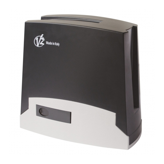
TORQ
I
ATTUATORE ELETTROMECCANICO
IRREVERSIBILE 230V PER CANCELLI
SCORREVOLI FINO A 800 KG
DI PESO
GB
230V ELECTRO-MECHANICAL
IRREVERSIBLE RACK ACTUATOR
FOR SLIDING GATES UP TO 800 KG
F
OPERATEUR ELECTROMECANIQUE
IRREVERSIBLE 230V POUR PORTAILS
COULISSANTS JUSQU'A 800 KG
DE POIDS
E
MOTOR ELECTROMECANICO
IRREVERSIBLES 230V PARA PUERTAS
CORREDERAS HASTA 800 KG
DE PESO
ZIS483
IL 509-1
EDIZ. 19/03/2019
Advertisement
Table of Contents

Related Manuals for V2 TORQ Series


Summary of Contents for V2 TORQ Series
- Page 1 ZIS483 IL 509-1 EDIZ. 19/03/2019 TORQ ATTUATORE ELETTROMECCANICO IRREVERSIBILE 230V PER CANCELLI SCORREVOLI FINO A 800 KG DI PESO 230V ELECTRO-MECHANICAL IRREVERSIBLE RACK ACTUATOR FOR SLIDING GATES UP TO 800 KG OPERATEUR ELECTROMECANIQUE IRREVERSIBLE 230V POUR PORTAILS COULISSANTS JUSQU’A 800 KG DE POIDS MOTOR ELECTROMECANICO IRREVERSIBLES 230V PARA PUERTAS...
- Page 2 325,5...
-
Page 3: Table Of Contents
INDEX 1 - 1 - GENERAL SAFETY INFORMATION ........................1.1 - PRELIMINARY CHECKS AND IDENTIFICATION OF THE TYPE TO BE USED ............1.2 - TECHNICAL ASSISTANCE SERVICE ........................1.3 - EU DECLARATION OF CONFORMITY ....................... 2 - TECHNICAL DATA ..............................3 - INSTALLATION OF THE MOTOR .......................... -
Page 4: General Safety Information
V2 customer assistance service. 1 - GENERAL SAFETY INFORMATION • V2 declines all responsibility for failure to comply with good construction practice standards in addition to structural deformation of the gate that might occur during use. -
Page 5: Preliminary Checks And Identification Of The Type To Be Used
1.1 - PRELIMINARY CHECKS AND IDENTIFICATION OF THE TYPE TO BE USED The automation device should not be used until installation, as specified in “Testing and start-up”, has been performed. It should be remembered that the device does not compensate for defects caused by improper installation, or poor maintenance, thus, prior to proceeding with installation, ensure that the structure is suitable and meets current standards and, if necessary, perform any structural modifications aimed at the implementation of safety gaps and the protection or segregation of all crushing, shearing and transit zones, and verify that:... -
Page 6: Technical Assistance Service
2014/30/UE (EMC); 2006/42/CE (MD) ANNEX II, PART B authorities’ request after justifiable request to: V2 S.p.A. The manufacturer V2 S.p.A., headquarters in Corso Principi di Corso Principi di Piemonte 65, 12035, Racconigi (CN), Italy Piemonte 65, 12035, Racconigi (CN), Italy... -
Page 7: Installation Of The Motor
3 - INSTALLATION OF THE MOTOR Wait for the complete setting of the concrete Unscrew the bolts fixing the base to the clamps and put the motor on the plate 3.1 - POSITIONING OF THE MOTOR Insert the 4 grains with their nuts in the proper place. Adjust the 4 grains to make the motor be perfectly levelled Control that the motor is perfectly parallel to the gate, then To fix TORQ, follow the instructions below:... -
Page 8: Mounting The Rack
3.2 - MOUNTING THE RACK Release the motor and turn the gate completely open. Fix all the rack elements to the gate, making sure that they stand at the same height than the motor pinion. The rack MUST BE positioned 1 or 2 mm over the pinion of the motor all the gate length. -
Page 9: Installing The Limit Switches
3.4 - INSTALLING THE LIMIT SWITCHES WARNING: For your safety, it is necessary that the gate is equipped with mechanical stoppers. WARNING: Once checked the proper working of the If the gate is not equipped with these stoppers, an erratic system, we suggest to weld the end-of-stroke brackets on movement past the range limit may cause the gate to fall. -
Page 10: Installation Layout
3.6 - INSTALLATION LAYOUT COMPONENTS ADDITIONAL ACCESSORIES Motor Key switch Transmitter Pillar photocells Photocells Pillar-mounted digital radio switch Flashing light Safety edges LENGTH OF THE CABLE < 10 metres from 10 to 20 metres from 20 to 30 metres Power supply 230V/120V 3G x 1,5 mm 3G x 1,5 mm 3G x 2,5 mm... -
Page 11: Control Unit
• Motor force adjustment with trimmer system in the closing phase it reopens • Incorporated radio receiver (433.92MHz), compatible with V2 fully. rolling transmitters The automation can re-close with the • 6 signalling LEDs (Paragraph 7). -
Page 12: Electrical Connections
6 - ELECTRICAL CONNECTIONS TRANSF PRI M RE F PH 01 PH 02 + VA GS I OL 1 CL 1 OL 2 CL 2 RADIO ST R START RADIO PHOTO ST P STOP ERROR START 1 2 3 4 5 6 7 8 OL 1 Power phase 230 VAC Opening limit switch... -
Page 13: Line Power Supply
6.1 - LINE POWER SUPPLY 6.5 - GATE OPEN PILOT LIGHT The “L” and “N” inputs are prearranged for the line voltage If the photo-test which is deactivated by default (see Paragraph connection. This must be 230Vac 50Hz. 11.1) is not used, it is possible to connect a gate status pilot light to the “GSI”... -
Page 14: Transmitter Programming
7 - TRANSMITTER PROGRAMMING 7.4 - DELETION OF A SINGLE TRANSMITTER Press the RADIO button for 4 seconds: the red “radio” LED If, at the start of the following procedures, the flashes “set”, “radio” and “start” LEDs flash, it means that the programming protections have been activated –... -
Page 15: Programming The Gate Path
8 - PROGRAMMING THE GATE PATH 8.2 - PROGRAMMING OF THE WIDTH OF THE PEDESTRIAN OPENING To start the system up, one of the following programming procedures must be carried out: Prior to proceeding with this programming procedure, basic programming of the automation’s movement: first verify whether either the “basic automation movement self-learning of the manoeuvre times and of the slowdown programming”... -
Page 16: Led Signalling
TRANSF PRI M 9. LED SIGNALLING 9.2 - ERROR SIGNALLING LEDS RED “ERROR” LED: With the control unit powered up (if control unit protection is The red “error” LED signals any errors that hamper the correct not activated) the yellow Set led flashes for 5 seconds and, if operation of the PCB. -
Page 17: Advanced Programming
ADVANCED PROGRAMMING 10.1 - PROGRAMMING OF THE BUTTON LINKED TO THE “AUX” OUTPUT The control unit has advanced programming that is not needed for commissioning the system but is useful for This procedure allows for programming the button of the radio configuring advanced system operations. -
Page 18: Selection Of "Aux" Output Operating Mode
10.3 - SELECTION OF “AUX” OUTPUT 11. SAFETY DEVICE ADVANCED OPERATING MODE PROGRAMMING SEQUENCES IF THE “AUX” OUTPUT IS SET AS LOCK the work mode These programming sequences are not essential to the system’s can be set as: operation, but they allow for controlling the safety devices ELECTRIC LOCK (default): at every command, the control unit by activating the photo-test when photocells are installed or closes the contact for 2 seconds... -
Page 19: Selection Of The Outputs Linked To The Photo-Test
11.2 - SELECTION OF THE OUTPUTS LINKED 12. SETTING THE WIRED COMMANDS TO THE PHOTO-TEST These programming sequences allow for locking wired commands, for managing the system solely with radio transmitters Default = PHO1 and PHO2 contacts or for changing the operation of the wired commands to start and With this procedure, it is possible to decide on which safety pedestrian. -
Page 20: Activating/Deactivating Start And Pedestrian Lock
12.2 - ACTIVATING/DEACTIVATING START 13. OTHER FUNCTIONS AND PEDESTRIAN LOCK To interrupt the following programming sequences at Default = wired start and start button on PCB activated. any time, press the SET and RADIO buttons simultaneously or wait 10 seconds. This programming sequence allows for locking the “start”... -
Page 21: F.a.q
The transmitter does not function When the programming sequence Verify the transmitter’s compatibility: the code must be V2. mentioned in Paragraph 7.1 is If the transmitter’s LED does not light up clearly, replace the completed, the red “radio” LED... -
Page 22: Testing And Start-Up
V2 recommends the application of the following technical The recommended interval between each maintenance operation standards: is six months, the checks involved should at least relate to: •... - Page 23 Are you satisfied? Should you wish to add another automation device to your home, contact the same installer and ask for a V2 SpA product: we guarantee you the most advanced products on the market and maximum compatibility with existing automation devices.
- Page 24 V2 S.p.A. Corso Principi di Piemonte 65/67 12035 RACCONIGI CN (ITALY) Tel. +39 0172 812411 - Fax +39 0172 84050 info@v2home.com www.v2home.com...
Need help?
Do you have a question about the TORQ Series and is the answer not in the manual?
Questions and answers
je voudrais programmer l'ouverture à droite sans la fermeture automatique