Table of Contents
Advertisement
Quick Links
ATTUATORE IDRAULICO PER CANCELLI A BATTENTE
I
HYDRAULIC ACTUATOR FOR SWING GATES
GB
ACTIONNEUR HYDRAULIQUE POUR PORTES BATTANTES
F
ACCIONADOR HIDRÁULICO PARA PUERTAS BATIENTES
E
ACCIONADOR HIDRÁULICO PARA PORTAS BATENTE
P
HYDRAULISCHER ANTRIEB FÜR DREHTÜREN
D
HYDRAULISCHE AANDRIJVING VOOR DRAAIHEKKEN
NL
V2 S.p.A.
URSUS
Advertisement
Table of Contents

Related Manuals for V2 URSUS Series


Summary of Contents for V2 URSUS Series
- Page 1 V2 S.p.A. URSUS ATTUATORE IDRAULICO PER CANCELLI A BATTENTE HYDRAULIC ACTUATOR FOR SWING GATES ACTIONNEUR HYDRAULIQUE POUR PORTES BATTANTES ACCIONADOR HIDRÁULICO PARA PUERTAS BATIENTES ACCIONADOR HIDRÁULICO PARA PORTAS BATENTE HYDRAULISCHER ANTRIEB FÜR DREHTÜREN HYDRAULISCHE AANDRIJVING VOOR DRAAIHEKKEN...
-
Page 3: Important Remarks
EN 60204-1, EN 12445, EN 12453, EN 13241-1, EN 12635 V2 has the right to modify the product without previous notice; it also declines any responsibility to damage or injury to people or things caused by improper use or wrong installation. - Page 4 PRELIMINARY CHECKS AND IDENTIFICATION OF THE TYPE TO BE USED Warning: The minimum safety level depends on the type of use; please refer to the following outline: Closure use type Group 1 Group 2 Group 3 Type of activation commands Group 1 - Group 2 - Group 3 -...
-
Page 5: Technical Data
TECHNICAL DATA URSUS-A Models (with mechanical slow down) MODEL DESCRIPTION URSUS-31 URSUS-A31 URSUS-A33 URSUS-A41 URSUS-A43 URSUS-31 URSUS-A41 URSUS-A31 URSUS-A43 URSUS-A33... -
Page 6: Installation Layout
INSTALLATION LAYOUT... - Page 7 INSTALLATION MEASURES WARNING: In the case of leaf longer than 2,5 metres, an electric lock must be fitted to ensure an efficent closig. INWARD OPENING URSUS-31 - URSUS-A31 - URSUS-A33 URSUS-41 - URSUS-A43 B [mm] C [mm] D [mm] E [mm] B [mm] C [mm] D [mm]...
-
Page 8: Installing The Operator
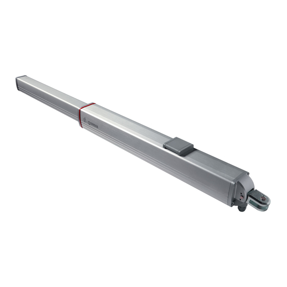
OUTWARD OPENING URSUS-31 - URSUS-A31 - URSUS-A33 URSUS-41 - URSUS-A43 B [mm] C [mm] D [mm] E [mm] B [mm] C [mm] D [mm] E [mm] 80° 80° 85° 85° 90° 90° 90° 90° 95° 95° 100° 100° 110° 110° INSTALLING THE OPERATOR The operator must work horizontally: to do this, the supports must be positioned with a height difference of 19 mm. - Page 9 A) - Position the front and rear supports The installer should choose the support attachment system (welding, screwing, molding, etc) in accordance with the composition of the material to which the supports are attached (metal, concrete, etc). Attach the supports on sufficiently robust structural elements.
- Page 10 C) - Mount the operator on the front support The mechanical slow down distance reduces as the ball bearing joint is unthreaded. The mechanical slow down distance increases as the ball bearing joint is threaded. D) - Mount the operator on the rear support Vertical pin: ø...
-
Page 11: Manual Operation
F) - Loosen the discharge screw G) - Mount the gland and introduce the cable If you have to dismount the operator from its supports, first tighten the discharge screw in order to prevent the hydraulic fluid from leaking. MANUAL OPERATION Unlock for manual operation Locking for automatic operation... - Page 12 CONNECT THE OPERATOR TO THE CONTROL UNIT Before making any electrical connections, check the switchboard instructions manual. Ensure the earth cable is properly connected. Before carrying out any gate movement, ensure there is no person or object in the radius of action of the gate and the drive mechanisms.
- Page 13 ADJUST THE OPENING AND CLOSING FORCE The opening and closing forces must be adjusted to fulfil standard EN 12453:2000. SELF LOCKING MODELS NONE LOCKING MODELS...
-
Page 14: Maintenance
TESTING AND START-UP MAINTENANCE Before carrying out any maintenance operation, disconnect the device from the power supply. If you have to dismount the operator from its supports, first tighten the discharge screw in order to prevent the hydraulic fluid from leaking. Force DISPOSAL OF THE PRODUCT Important! –...
Need help?
Do you have a question about the URSUS Series and is the answer not in the manual?
Questions and answers