Table of Contents

Related Manuals for Vivax Metrotech vLoc-5000


Summary of Contents for Vivax Metrotech vLoc-5000
- Page 1 User Handbook (English Edition) Version V1.1 Toll-Free: 800-WCT-PROD (928-7763) Local Phone: 310-822-5212 Fax: 310-306-9343 Email: info@wctproducts.com Address: 13309 Beach Ave. Marina del Rey, CA 90292 Website: www.wctproducts.com...
-
Page 2: Table Of Contents
vLoc-5000 Receiver ........................6 Charging the Receiver Batteries ....................7 vLoc-5000 Receiver Main Display and Pushbutton ..............8 vLoc-5000 Receiver Screen Shots ..................... 9 Distance Sensitive Left/Right Guidance™ Display ..............9 ... - Page 3 Trimble ProXT/XH ........................17 4.3.1 Trimble ProXT/XH Setting up Procedure ................17 4.3.2 Transferring Data from the vLoc-5000 to a Computer ............19 MyLocator2 ..........................19 4.4.1 Launch the Application ...................... 19 ...
- Page 4 Using the Receiver ........................35 6.1.1 Line Locating ........................35 6.1.2 Depth & Current Measurement ..................35 6.1.3 Sonde Location ........................36 6.1.4 Using the Compass Feature to Locate Sondes ..............36 ...
- Page 5 7.15 Ground Spool (Optional) ......................54 7.16 Banana Plugs Adapter (Optional) ..................... 54 7.17 Loc-5Tx/10Tx Charger ......................55 7.18 Loc-10Tx Rechargeable Battery Tray ..................55 7.19 Loc-10Tx Alkaline Battery Tray....................55 ...
-
Page 6: General Safety & Care Information
1 General Safety & Care Information General Safety & Care Information Who Can Use This Equipment This equipment must only be used by people suitably trained in the use of pipe and cable locators. Work-site Safety Use your companies, or other applicable safety code and rules when using this equipment. ... -
Page 7: Lithium-Ion Batteries (Rechargeable)
1 General Safety & Care Information the rechargeable batteries for at least 10 minutes before recharging. If this reoccurs the next time the unit is charged – return immediately to Vivax-Metrotech for repair. Do NOT charge batteries for prolonged periods of time without using the locator for at least 10 mins. Charging for prolonged period of time could overcharge the battery, reduce the battery life and in extreme circumstances cause damage to the locator and fire. -
Page 8: Care When Interpreting The Information Provided By The Locator
1 General Safety & Care Information Care When Interpreting the Information Provided by the Locator Like all locators – this instrument is locating, and providing depth and current readings based on electromagnetic signals that radiate from the buried cable or pipe. In most cases these signals will enable the locator to pinpoint both position depth and current correctly. -
Page 9: Service & Support
2 Service & Support Service & Support Serial Number and Software Revision Number Always quote your receiver and transmitter model number, serial number and software revision number when requesting product support. They can be found as follows: (for reference only) Model&... -
Page 10: Distributors And Service Centers Closest To You
2 Service & Support Distributors and Service Centers Closest to You: United State of America Europe Vivax-Metrotech Corporation SebaKMT 3251 Olcott Street, SebaDynatronic Santa Clara, CA 95054, USA Mess-und Ortungstechnik GmbH Website : www.vivax-metrotech.com Dr.-Herbert-Iann-Str. 6, 96148 Baunach, Germany Sales & Sales Support: T/Free : +1-800-446-3392 : +49-9544-680... -
Page 11: Vloc-5000 Receiver
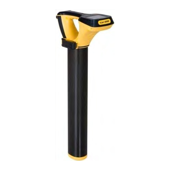
3 vLoc-5000 Receiver vLoc-5000 Receiver vLoc-5000 Receiver The vLoc-5000 is a Precision Location System designed to meet the needs of Utility Companies and their contractors. The following describes the features and use of the receiver: Optional Bluetooth Module Charging Socket Pushbutton &... -
Page 12: Charging The Receiver Batteries
3 vLoc-5000 Receiver Charging the Receiver Batteries The vLoc-5000 can be used with either alkaline batteries or it can be supplied with an interchangeable rechargeable battery pack. Icon A Icon B When alkaline battery is used, Icon A will appear on the screen. When the rechargeable battery pack is used, Icon B will be displayed. -
Page 13: Vloc-5000 Receiver Main Display And Pushbutton
3 vLoc-5000 Receiver vLoc-5000 Receiver Main Display and Pushbutton The vLoc-5000 has several display options – the display shown below is representative of the types of display and icons used. Digital Display of Signal Response Gain Control (increase gain) Loudspeaker Status... -
Page 14: Vloc-5000 Receiver Screen Shots
Main Display Main Menu The vLoc-5000 is a Precision Location System designed to meet the needs of Utility Companies and their contractors. The following describes the features and use of the receiver. Distance Sensitive Left/Right Guidance™ Display The Left/Right display is tremendously useful in refining the precise location of the target line. -
Page 15: Locating Mode (Response)
Distance Sensitive Left/Right Guidance Locating Mode (Response) The vLoc-5000 receiver has four antennas, and these can be toggled through different configurations (modes) to provide different responses to the signals radiating from the buried pipes and cables. The modes are: 3.5.1... -
Page 16: Broad Peak Mode
3 vLoc-5000 Receiver 3.5.2 Broad Peak Mode This uses a single horizontal antenna and provides a “Peak” or maximum signal response over the center of the radiated signal from the buried line. The compass line direction indicator shows the direction of the cable (available in Active modes). -
Page 17: Audio
Frequency Selection The vLoc-5000 receiver is capable of locating a large number of frequencies or frequency combinations. A list of these frequencies can be accessed using the setup menu. Most of these frequencies listed – you will never use –... -
Page 18: Information Pushbutton (Depth & Current)
3 vLoc-5000 Receiver select pushbutton on the main receiver pad is used to toggle through the frequencies defined using the setup menu. The operating frequency will be shown at the lower right side of the display. You can change this selection at any time using the setup menu. -
Page 19: Information Pushbutton (Setup Menu)
3 vLoc-5000 Receiver 3.11 Information Pushbutton (Setup Menu) Pushbutton As described previously, a second function performed by the “i” is to access the SETUP menu. Press and hold the “i” pushbutton for two seconds to display the SETUP menu. Use the “+”,“-” to navigate through the various options and use the “M”... -
Page 20: Data Logging
4 Data Logging Data Logging The vLoc-5000 has an internal memory that can be used to store location data. It can store in excess of 1000 records. To store a record first locate a point of interest. Hold the vLoc stationary over the target and press the “i”... -
Page 21: Holux Gps Device Overview
It can either be mounted in the purpose designed holder from Vivax-Metrotech or can be positioned anywhere within a few meters from the vLoc-5000. For instance using “Velcro” to attach it to the peak of a baseball cap ensures clear view of the sky and satellites. -
Page 22: Gathering Data In Active Modes
Transferring Data from the Locator to a Computer To transfer data it is necessary to use the vLoc-5000 Configurator Tool. This is a simple program that can be downloaded from the Vivax-Metrotech web site at www.vivax-meterotech.com. The file can be found under the Support/Download Library/Others Download. - Page 23 4 Data Logging http://www.trimble.com/pathfinderproxt_ts.asp?Nav=Collection-32840 Connect the Trimble ProXT to your computer either by setting up a Bluetooth connection or by using the RS232 lead supplied. Launch the application and switch on the GPS. When connection is achieved a little satellite icon will appear in the middle of the top bar.
-
Page 24: Transferring Data From The Vloc-5000 To A Computer
Transferring Data from the vLoc-5000 to a Computer To transfer data from the vLoc-5000 receiver to a computer requires the use of a simple free of charge software package MyLocator2. It can be downloaded from the Vivax-Metrotech web site www.vivax- metrotech.com. -
Page 25: Splash Screen
4 Data Logging The basic operational screen is displayed below. This will change slightly depending on which tab is active. Connect the vLoc receiver to the PC using a USB to Mini USB cable. The PC should recognize the vLoc and the display will now change to the below or similar. -
Page 26: Upload Data Files
4 Data Logging 6. Text can also be added to the flash screen. 7. Use the “Text”, “BG Color” (Background color) and “Font” buttons to add text to the startup flash screen. 4.4.3 Upload Data Files 1. Click on the “Import Data” tab. A screen similar to the one below should be shown. 2. -
Page 27: Software Update
4 Data Logging 4.4.4 Software Update 1. With the locator switched on and connected to the computer, click on the “Software Update” tab. 2. A screen similar to the one below should be shown. 3. If connected to the Web, press the “Get latest swrev” button. Alternatively, if the software revision required is already saved, use the “File”... -
Page 28: Switch On/Off User Menu Settings
4 Data Logging By doing this the locator is simplified and tailored exactly to the customer requirements. The configuration can be saved as a “configuration” file and used to configure other vLoc-5000 locators. This ensures consistency throughout the locator fleet. -
Page 29: Saving A Configuration
4 Data Logging c. Green indicates that the frequency will be available both in the locator menu and frequency select key. d. Blue shows active line. 3. Make the selections required. 4. Clicking on the “Send Cfg” icon will send the configuration to the locator. 4.4.8 Saving a Configuration Having created a configuration it is possible to save this for future use. - Page 30 4 Data Logging The features can only be re activated by connecting to a host computer with MyLocator2 which has been dongle activated. Double click on the padlocks as before to unlock them and download the changes to the locator. Example use of the Dongle Lock: Supposing the Dongle User wishes to force the user to only use 8 kHz Peak Mode.
-
Page 31: 4.4.10 Icon Summary
4 Data Logging 4.4.10 Icon Summary Icon Function Opens a previously saved configuration. Saves a configuration created by the operator to a file of your choice. Either “Send” (saves) configuration to a locator or “Get” (copy) a configuration from a locator. -
Page 32: Loc-10Txsis Transmitter
5 Loc-10TxSIS Transmitter Loc-10TxSIS Transmitter Loc-10TxSIS Transmitter Overview The Loc-10TxSIS transmitter is a rugged portable transmitter powered by alkaline “D” cells or Ni-MH (Nickel Metal Hydride) rechargeable batteries. The following describes the features and uses of the transmitter. Display Frequency Being Transmitted (200 kHz Output Setting (Step) (filled box indicates available in some country) current level has been reached, empty box... -
Page 33: Transmitter Battery
5 Loc-10TxSIS Transmitter Transmitter Battery In most markets the transmitter is shipped with alkaline batteries (12 x D cells) unless rechargeable batteries are specified. Batteries are fitted into quick release trays – the alkaline is an open pack, to enable the batteries to be changed. -
Page 34: Re-Fitting The Battery Tray
5 Loc-10TxSIS Transmitter 5.2.4 Re-fitting the Battery Tray Place top of catch over catch plate Push up button underneath the catch – where holding that up push in the bottom of the catch. You will hear a positive “click” (Do NOT force catches) To close battery tray –... -
Page 35: Direct Connection Mode
5 Loc-10TxSIS Transmitter Icon “Induction” mode is generally used when no access is available to make a direct connection, or a clamp connection. When using induction it is very likely that the signal being induced onto the target line will also be induced onto other lines in the area, and onto above ground features such as wire fences. -
Page 36: Clamp Mode
5 Loc-10TxSIS Transmitter 5.3.3 Clamp Mode Plugging the signal clamp supplied by Vivax-Metrotech into the output socket will place the transmitter in “Clamp” mode. An icon confirming this is displayed on the display. The icon flashes when the transmitter is transmitting. -
Page 37: Frequencies And Power Output
5 Loc-10TxSIS Transmitter 5.3.5 Frequencies and Power Output TheLoc-10TxSIS transmitter is supplied with a predefined set of transmit frequencies. Standard frequencies are: 512Hz (where electrical systems are 60Hz) direct connection – 10 watts. 640Hz (where electrical systems are 50Hz) direct connection – 10 watts. ... -
Page 38: Dual Frequency" Mode
5 Loc-10TxSIS Transmitter To enter the "Frequency Menu" proceeds as follows: 1. Press the “i" pushbutton 5 times to get to the "Frequency selection" sub-menu. 2. Screen will show a list of frequencies available, with the central one in a box. 3. -
Page 39: Information
5 Loc-10TxSIS Transmitter 4. Press "f" pushbutton to select the second frequency and exit the submenu to return to the main display. 5. In the main display screen, both frequencies are displayed. The frequency will toggle between the two chosen frequencies. NOTE If user is changing the selected frequency by pressing the "f"... -
Page 40: Using The Vloc-5000
6 Using the vLoc-5000 Using the vLoc-5000 Using the Receiver 6.1.1 Line Locating Line locating is when a pipe or cable is being located. When line locating, the receiver should be held with the display forward, and then swept to the left and right across the suspected direction of the buried line. Note the compass line direction indicator always points in the direction of the line (active in active modes). -
Page 41: Sonde Location
6.1.4 Using the Compass Feature to Locate Sondes Switch on the vLoc-5000. Select the frequency to match the Sonde frequency. Use the mode pushbutton to select Sonde. Stand in the approximate vicinity of the Sonde. Press the “+” pushbutton to increase the gain so that a steady bar graph reading is displayed. - Page 42 6 Using the vLoc-5000 To pinpoint the Sonde, find the peak in both directions. When over the peak position, the depth is automatically displayed. Press the “i” pushbutton to get a more precise depth reading. Using the compass to locate the Sonde requires free space to walk to the side of the Sonde. If there is an obstacle such as a wall or vehicle that restricts walking in an arc, the following method can be used.
-
Page 43: Passive Or Active Location
6 Using the vLoc-5000 Pinpoint the Sonde as in the first procedure. Passive or Active Location There are two types of location method available with this system, they are: 6.2.1 Passive Locating Passive locating is locating buried utilities using the electromagnetic signals that exist in the environment. We group these under two settings: ... -
Page 44: Applying The Transmitter's Signal
6 Using the vLoc-5000 This receiver provides a wide range of frequencies for active location. Some will be the same as the frequencies provided by the Vivax-Metrotech’s transmitter, others will be frequencies used in other manufacturers’ transmitter. The choice of frequencies when using induction or the clamp is restricted due to the requirement that these modes be tuned for specific frequencies (or range of frequencies). -
Page 45: Clamp (Coupler)
6 Using the vLoc-5000 WARNING BE CAREFUL not to hit other buried lines when inserting the ground stake into the ground. Check using passive location prior to inserting ground stake. Stop if additional resistance is felt during insertion. 6.3.2 Clamp (Coupler) This is used when applying the transmitter signal to cables carrying hazardous voltages, or cables where access to the metallic conductor is not possible, or desirable. -
Page 46: Searching (Sweeping) An Area
6 Using the vLoc-5000 from the cable, resulting incorrect information. 6.3.4 Searching (Sweeping) an Area In any given area, it is likely that buried pipes and cables are not parallel to each other, frequently they will cross the area being searched at a variety of different angles and depths. As the response of locator antennas is directional, it is important to search the area in the same or similar pattern as below. -
Page 47: Pinpointing & Confirming The Buried Line
6 Using the vLoc-5000 6.3.6 Pinpointing & Confirming the Buried Line Marking the exact position of the buried line is generally called pinpointing. Pinpoint the line before marking its position. Place the receiver in “Peak” or “Left/Right” mode, pass the blade of the receiver across path of the cable and identify the peak response on the display and/or audibly. - Page 48 6 Using the vLoc-5000 An alternate method of verifying depth (D) is triangulation which must be done Broad peak mode. There are two methods of triangulation, 50% and 70% rules. On some models there is an option that instructs the user in taking triangulation measurements.
-
Page 49: Cable Tracing Using Signal Select Or Signal Direction Signals
6 Using the vLoc-5000 WARNING NEVER mechanically dig over the path of a buried pipe or cable. ALWAYS dig carefully. 6.3.9 Cable Tracing using Signal Select or Signal Direction Signals Energizing cables or pipe with a known signal enables them to be traced with a certain degree of confidence. -
Page 50: 6.3.10 Signal Direction Precision Identification
6 Using the vLoc-5000 the red filling is at a lower level in the Guidance Compass in these areas. The measured distortion approaches a peak about in the same place as the signal strength peak, indicating the presence of another conductor. - Page 51 6 Using the vLoc-5000 As a result there can be multiple signals radiating from cables and pipes in the area making it difficult to identify the target line. These return signals are typically traveling in the opposite direction than the applied signal.
-
Page 52: Using The Accessories
6 Using the vLoc-5000 At some point you may find that the SD icon and start flashing – this is indicating that synchronization with the transmitter has deteriorated and a reset is required. Re-trace your line back to a point where a solid signal direction is obtained. Precisely pinpoint the line and stand with your back to the direction of the transmitter as you did when you initiated the original sync and press the “i”... -
Page 53: Using The A-Frame In Fault Finding
The A-frame cannot distinguish between these two situations. After isolating the line, use the vLoc-5000 transmitter resistance measuring function, or a dedicated resistance measuring device to confirm that there is a fault to ground. The A-frame will typically detect faults up to 2 mega ohm and above (depending on the distance from transmitter, soil conditions etc). - Page 54 6 Using the vLoc-5000 Image for reference only and may differ from actual image Remove the plastic spike covers from the A-frame. Walk along the route of the line placing the spikes of the A-frame in the ground (with the green leg pointing away from the transmitter connection point) every two or three paces.
-
Page 55: Using The Remote Antenna Usb
6 Using the vLoc-5000 6.4.3 Using the Remote Antenna USB The remote stethoscope antenna can be used to help identify a particular cable on a cable tray or where cables are bunched together. Methods: 1. Connect a signal to the cable to be identified. The remote stethoscope functions has an operational frequency range of 512Hz up to 200kHz, but low frequencies should be a preference in this application as they are less likely to leak or bleed over to other cables. - Page 56 6 Using the vLoc-5000 7. Ensure the frequency selected on the vLoc is the same as selected on the transmitter. 8. Place the stethoscope on each of the suspected target cables with the flats of the antenna in line with the route of the cable.
-
Page 57: Accessories & Options
7 Accessories & Options Accessories & Options A-frame (Optional) The A-frame accessory is used to detect ground faults on pipes and cables. In the case of pipes, the faults consist of coating defects. In the case of cables, faults are usually caused by insulation damage allowing the metallic sheath (or internal conductor) to become in contact with the ground. -
Page 58: Receiver Vehicle Charging Lead(Optional)
7 Accessories & Options Receiver Vehicle Charging Lead(Optional) 12ft (4m) long lead to charge the receiver’s battery (Lithium-ion) while on the move. It is preferable to connect the charger to a cigarette lighter socket that is permanently live. However, do NOT leave connected to the receiver for excessively long periods. -
Page 59: Receiver Battery Charger (Standard)
7 Accessories & Options 7.10 Receiver Battery Charger (Standard) The receiver Lithium-ion battery charger is supplied as a standard item. It is powered from the mains supply (100-250V AC) 7.11 USB Cable (Standard) The USB cable is used to connect the receiver to a host computer so that software updates can be implemented and also for the transfer of data logs from the unit to a computer. -
Page 60: 7.17 Loc-5Tx/10Tx Charger
7 Accessories & Options 7.17 Loc-5Tx/10Tx Charger Mains charger (100-250V AC input) used to charge 5 Watt or 10 Watt rechargeable battery packs. Supplied as standard with rechargeable battery option. 7.18 Loc-10Tx Rechargeable Battery Tray NiMH rechargeable battery pack. Only use the charger supplied. 7.19 Loc-10Tx Alkaline Battery Tray Requires 12 x Alkaline D cells. -
Page 61: Glossary
8 Glossary Glossary Active Locate A locate where a transmitter is used to apply a signal to a buried pipe or cable, the position of which is then located by a receiver tuned to the same frequency. Active Signal A signal applied by the locator transmitter to a buried line. Typical this is a very precise frequency. - Page 62 8 Glossary hence whatever it is attached to or in. Frequently used for locating sewer cameras, and the non metallic pipes. Target Line The buried pipe or cable to be located. Trace Using a locator to following the path of a buried line. Illustrations used in the preparation of this manual will inevitably show some resemblance to similar illustrations from other Manufacturers-some manufacturers have given permission for the use of their graphics (Vivax-Metrotech &...
- Page 63 Notes: _________________________________________________________________ _________________________________________________________________ _________________________________________________________________ _________________________________________________________________ _________________________________________________________________ _________________________________________________________________ _________________________________________________________________ _________________________________________________________________ _________________________________________________________________ _________________________________________________________________ _________________________________________________________________ _________________________________________________________________ _________________________________________________________________ _________________________________________________________________ _________________________________________________________________ _________________________________________________________________ _________________________________________________________________ _________________________________________________________________ Vivax-Metrotech Corporation 3251 Olcott Street, Santa Clara, CA 95054, USA Website: www.vivax-metrotech.com info@wctproducts.com | 13309 Beach Ave. Marina del Rey, CA 90292 | Phone: 800-WCT-PROD (800-928-7763) | Fax: 310-306-9343...
Need help?
Do you have a question about the vLoc-5000 and is the answer not in the manual?
Questions and answers