Vivax Metrotech vLoc3-Pro User Handbook Manual
Hide thumbs
Also See for vLoc3-Pro:
- Training (185 pages) ,
- User handbook manual (68 pages) ,
- Quick manual (2 pages)

Related Manuals for Vivax Metrotech vLoc3-Pro


Summary of Contents for Vivax Metrotech vLoc3-Pro
- Page 1 Locators & Supplies, Inc. (800) 950-6666 sales@locatorsandsupplies.com www.locatorsandsupplies.com vLoc3-Pro User Handbook (English Edition) Version 1.2 P/N: 4.04.000105...
-
Page 3: Table Of Contents
American & Canadian Safety Notices .......................3 Service & Support...............................4 Serial Number and Software Revision Number ..................4 Distributors and Service Centers Closest to You: ..................5 vLoc3-Pro Receiver ............................6 vLoc3-Pro Receiver Overview ........................6 Charging the Receiver Batteries .......................7 vLoc3-Pro Receiver Keypad ........................8 User Menu ..............................8 3.4.1 About ............................9... - Page 4 3.6.4 Overhead cable .........................12 vLoc3-Pro Receiver Locate Screen Shots ....................12 Classic Locating Modes (Response) ......................14 3.8.1 Peak Response Mode ......................14 3.8.2 Broad Peak Mode ......................14 3.8.3 Null Mode .........................15 3.8.4 Delta Null .........................15 3.8.5 Peak with Arrows Response Mode ..................15 3.8.6...
- Page 5 5.3.8.1 Supervisor Lockouts ....................44 Loc3-10Tx Transmitter............................45 Loc3-10Tx Transmitter Overview ......................45 6.1.1 Display ............................45 6.1.2 Pushbuttons..........................46 6.1.3 Information Pushbutton ......................46 6.1.4 Connections Block ........................46 Transmitter Battery ..........................47 6.2.1 Removing the Battery Tray ......................47 6.2.2 Replacing the Alkaline Battery ....................47 6.2.3 Rechargeable Batteries ......................48 6.2.4 Re-fitting the Battery Tray ......................48 6.2.5...
- Page 6 Using the Accessories ............................68 Using the LPC Separation Filter ......................68 Using the Analogue A-frame Fault Finding Accessory ................68 Using the vLoc3-Pro Remote Antenna ....................71 Using the SD Signal with the Remote Antenna to help trace a particular cable ........74 Accessories & Options............................77 A-frame ..............................77...
-
Page 7: General Safety & Care Information
General Safety & Care Information General Safety & Care Information Who Can Use This Equipment ● This equipment must only be used by people suitably trained in the use of pipe and cable locators. Work-site Safety ● Use your company’s, or other applicable safety codes and rules when using this equipment. ●... -
Page 8: Lithium-Ion Batteries (Rechargeable)
General Safety & Care Information ● If ever the product becomes hot during the charging process, immediately unplug the charger and use the rechargeable batteries for at least ten minutes before recharging. If this reoccurs the next time the unit is charged – return immediately to Vivax-Metrotech for repair. -
Page 9: Care Of Equipment
General Safety & Care Information Care of Equipment ● Use equipment only as directed in this User Handbook. ● Do not immerse any part of this equipment in water. ● Store in a dry place. ● Keep equipment in the case provided when not in use. ●... -
Page 10: Service & Support
Service & Support Service & Support Serial Number and Software Revision Number Always quote your receiver and transmitter model number, serial number and software revision number when requesting product support. They can be found as follows: (for reference only). Model & Serial Number NOTE The transmitter Model &... -
Page 11: Distributors And Service Centers Closest To You
Service & Support Distributors and Service Centers Closest to You: World Headquarters, United State of America Central/South America and the Caribbean Vivax-Metrotech Corporation Ventas para América Latina 3251 Olcott Street, 3251 Olcott Street, Santa Clara, CA 95054, USA Santa Clara, CA 95054, USA Website : www.vivax-metrotech.com T/Free : 800-624-6210... -
Page 12: Vloc3-Pro Receiver
Receiver vLoc3-Pro Receiver vLoc3-Pro Receiver Overview The vLoc3-Pro is a Precision Location System designed to meet the needs of utility companies and their contractors. The following describes the features and use of the receiver. vLoc3-Pro receiver Mini-USB cable Li-ion battery... -
Page 13: Charging The Receiver Batteries
Receiver Charging the Receiver Batteries The vLoc3-Pro can be used with either alkaline batteries or an interchangeable rechargeable battery pack. The central illuminated section within the battery icon indicates the amount of charge remaining. ● Blue centre indicates alkaline batteries. -
Page 14: Vloc3-Pro Receiver Keypad
User Menu The vLoc3-Pro has several features that can be switched on and off. These features are accessed through the user menu. Switch on the unit by pressing and holding the On/Off key until the start-up screen appears. The start-up screen can be configured to the user’s preference and is described later in the manual. -
Page 15: About
Self Test Main Menu Note that the manual shows three screens but only one is shown on the vLoc3-Pro display at a time. Note that where you see this sign it means that pressing the enter button gives access to the sub-menu associated with this button. -
Page 16: Classic Locate
Receiver Note also that certain frequency options have an A-frame icon next to them. This indicates that these frequencies are selected to be used with the fault find A-frame. 3.4.6 Classic Locate This option is only shown if the User menu is entered from the Classic Screen. -
Page 17: Self-Test
Metrotech Corporation or one of its authorised service centres for repair. Self-Test The vLoc3-Pro has a self-test feature. The test confirms that the equipment is fit for use and calibration has not drifted from its expected settings. To undertake the test, first find an area free from excessive interference such as overhead fluorescent lighting, large transformers etc. -
Page 18: Swing Alert
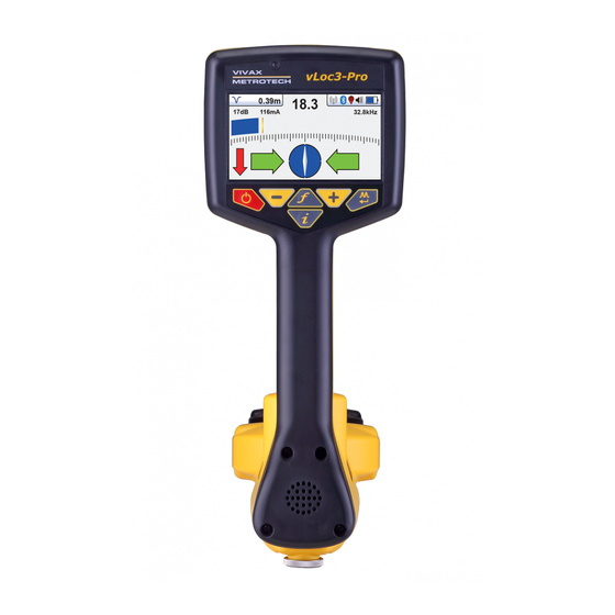
The user interface of the vLoc3-Pro is under continual development. The screen shots described may differ slightly from current screens. The vLoc3-Pro gives the user a choice of different locate screens. The choice of screen depends on application and user preference. - Page 19 Receiver Bluetooth status GPS status Speaker volume setting Battery type and remaining charge The Classic Screen has all the functions normally seen on a classic cable locator. The main functions being: 18.3 0.39m 17dB 116mA SD-USA Percentage signal strength (mirrors the bar graph setting)
-
Page 20: Classic Locating Modes (Response)
Classic Locating Modes (Response) The vLoc3-Pro receiver has an array of six antennas, and these can be toggled through different configurations (modes) to provide different responses to the signals radiating from buried utilities. The modes are: 3.8.1... -
Page 21: Null Mode
Receiver 3.8.3 Null Mode This uses vertical antennas, and provides a minimum or “Null” response over the center of the buried line. The compass (line direction indicator) aligns itself parallel to the direction of the cable (available in Active modes) The null mode works well in uncongested areas but is more prone to inaccuracies due to the effects of field distortion. -
Page 22: Omni Peak Response Mode
When taking depth measurement, always hold the receiver at 900 to the ground. Alternative Locate Screens As previously mentioned, the vLoc3-Pro has a number of alternative screens. The following section describes operation these screens. It is left to the user to decide which is the best screen for a particular application. - Page 23 Receiver Specific mode for detecting and locating sonde transmitters. Sonde Vector Shows a cross section of the ground and line position relative to the locator. configuration Plan view Gives a plan view as if looking into the ground. Shows a graphical representation of the peak and null field shape over a line (Active Trans.
- Page 24 Receiver The cross-sectional section of the screen will respond as the target is approached. Use the + and – keys to alter the scaling if necessary. There is a black line leading from the locator to the target line. The target is represented by a blue dot. Around the dot is a circle, the size of the circle indicates a confidence factor.
- Page 25 Receiver Using the Plan View screen. Apply the signal to the target line in the usual way and select the plan view screen by using long presses on the return button until the desired screen appears. Position the locator within the approximate position of the target line. Use the plan view to help guide you toward the target line.
- Page 26 Receiver In non-distorted fields, the peak and null positions should coincide and the shape of the fields should be symmetrical about the center line. The picture below shows a slightly distorted field. 3’9” 33dB 14.1mA 8.19kHz To take a plot first locate the target using one of the other locate screens. Now select the Transverse screen by a prolonged press of the return button.
-
Page 27: Using The Vloc3-Pro
Using the vLoc3-Pro Using the vLoc3-Pro Using the Receiver Line Locating - Using the “Classic” Screen. 69.1 25dB 640Hz Passive Locating NOTE The compass indicator is not active during passive location. Passive locating refers to the process of detecting signals that “naturally” occur on pipes and cables. These tend to fall into two categories, radio signals and power signals. -
Page 28: Detecting Power Signals
Keeping the vLoc3-Pro vertical, walk across the area to be checked keeping the orientation so that the blade is in line with the direction of walking (See diagram above). If using the Onmi Peak mode the orientation of the locator is not important. -
Page 29: Detecting Radio Signals
Using the vLoc3-Pro Rotate the vLoc3-Pro on its axis to obtain the maximum signal. The vLoc3-Pro is now directly over the line and with the blade across the line. (If using the Omni-Peak mode there will be no change so switch to Peak mode if the direction is required). - Page 30 Using the vLoc3-Pro WARNING Only authorized personnel should make connections to cables. To make a direct connection, insert the direct connection connector to the transmitter. Insert the ground stake into the ground a few meters perpendicular to the line. Connect the black lead to the ground stake. Now take the red lead and connect to the target line.
-
Page 31: Signal Clamp (For Frequencies Above 8Khz)
Using the vLoc3-Pro 4.3.2 Signal Clamp (for frequencies above 8kHz) In many situations, it is not possible to gain access to a cable to make an electrical contact. Or if there is, it is not safe to do so. The signal clamp provides an efficient and safe method of applying a locate signal to a cable. -
Page 32: Induction (For Frequencies Above 8Khz)
With no direct connection lead or signal clamp connected, the transmitter will automatically start to radiate a signal around the transmitter. These signals will penetrate the ground and couple onto buried lines. The signal will then travel along the line which can be detected with the vLoc3-Pro locator. Applying an induction signal to a line. -
Page 33: Locating Active Signals
It may be necessary to reduce the sensitivity to keep the bar graph on scale. This is normal and should be expected. Try to keep the vLoc3-Pro vertical and avoid swinging it as this may create false readings. -
Page 34: Searching (Sweeping) An Area In The Peak Mode
Using the vLoc3-Pro If the signal is not distorted, the position of maximum signal will coincide with the position as indicated by the arrows. If these two positions do not agree, it may be because there is signal distortion. Treat the results with caution. -
Page 35: Depth & Current Measurement
If the depth measurement feature is activated, it is possible to take depth measurement estimations. To take a depth measurement, first pinpoint the position of the line as above. Place the tip of the vLoc3-Pro on the ground making sure it is vertical and across the line i.e. -
Page 36: Sonde Location Mode
Using the vLoc3-Pro Null Position True Position Peak Position • ● Measure the depth of the buried line by pressing “i” pushbutton briefly to measure depth and current. The depth should be approximately in line with the “as built” plans available. If no plans are available logic would still help to assess the situation (for instance, if you are looking for a shallow CCTV distribution cable and the depth indicated is 5ft (1.5m) it should raise a... - Page 37 – a small peak with two “Nulls” between the peaks. The sonde is located under the center of the “large peak” The vLoc3-Pro detects the presence of the two “Null” signals and also the position of the main “Large Peak”. It uses this information to provide a reliable and efficient method of sonde location.
-
Page 38: Signal Direction Precision Identification
4.11 Signal Direction Precision Identification (Available for vLoc3-Pro with SD and vLoc3-ML models only) Some models in the vLoc series of locators contain a feature called “SIGNAL DIRECTION”. This feature is used to verify if the line being located is the target to which the transmitter has been connected. - Page 39 Using the vLoc3-Pro ● Turn the transmitter and receiver on, and set both to: ο SD-USA – if in North America or any territory where the power system is 60Hz. ο SD-EUR – if in Europe or any territory where the power system is 50Hz.
- Page 40 Using the vLoc3-Pro ● Re-trace your line back to a point where a solid signal direction is obtained. Precisely pinpoint the line and stand with your back to the direction of the transmitter as you did when you initiated the original sync, and press the “i” pushbutton then the enter/return pushbutton to re-sync with the transmitter signal.
-
Page 41: Data Logging
Data Logging Data Logging The vLoc3-Pro has an internal memory that can be used to store locator data. Available storage size is four Gigabyte which relates to many thousands of records. The records are user initiated. These are records stored by the user whenever the “+” button is pressed when in the “Information” screen. -
Page 42: Bluetooth
● Switch on the external device. ● Switch on the vLoc3-Pro and enter the User setup menu by a long press on the “i” button. ● Use the “+” and “-” keys to scroll down to the option “Bluetooth Pairing”. -
Page 43: Transferring Data From The Locator To A Computer
(see previous section on Bluetooth devices). Once paired with an external device, the vLoc3-Pro will await valid GPS data from the external device. The GPS icon will turn green when a valid GPS signal is detected. This can take from a few seconds to a few minutes depending on the device and whether it is doing a “cold”... -
Page 44: My Locator3'S Basic Operation
Data Logging 5.3.2 My Locator3’s Basic Operation MyLocator3 operation, not requiring a USB security dongle. 5.3.2.1 Updates Page When a locator is first connected to the PC, the “Updates Page” will be displayed and this will show the locator variant type along with the locator serial number and the running firmware version in the upper left-hand box. -
Page 45: 5.3.2.3 Locator Firmware Update
Data Logging 5.3.2.3 Locator Firmware update Each time a locator is connected to the PC, it’s firmware version is checked against the latest version available on the Vivax- Metrotech server and the user is notified if an update is available as shown below. This feature will only be available if the computer is “online”. -
Page 46: Toolbar
Toolbar The vLoc3-Pro locator can be configured so that features can be switched on or off. This enables the user to tailor the instrument to meet the needs of their application while keeping the user interface uncluttered. The toolbar at the top of the screen enables the user to create configurations. -
Page 47: Splash Screen
Data Logging 5.3.5 Splash Screen On this page an image can be loaded which can be used as a splash screen by the locator when it is switched on. The locator has an LCD screen with a resolution of 480 by 272 pixels. The image loaded into MyLocator3 will be scaled to fit the width of the screen. -
Page 48: Frequencies Page
Data Logging 5.3.6 Frequencies Page The “Frequencies” page will allow the user to refine which frequency modes are available when the locator F-key is pressed and which frequencies appear on the locator menu. ™ Page 42 of 81... -
Page 49: Menu Settings
Data Logging 5.3.7 Menu Settings The “Menu Settings” page allows the user control over which menu items appear on the locator and also the initial setting of the menu item when the locator is first used after configuration. The menu items with a right pointing arrow can be expanded to reveal further sub-menu items. -
Page 50: Advanced Features
Data Logging 5.3.8 Advanced Features The Advanced Features are available to those users in possession of a USB security dongle. If a dongle is attached to the PC then its level will be displayed on the MyLocator3 status bar. 5.3.8.1 Supervisor Lockouts This feature is available to anyone with a dongle (contact Vivax-Metrotech for the purchase of a dongle).When a dongle is connected to your computer via a standard USB socket, the icons for the “Splash Screen”... -
Page 51: Loc3-10Tx Transmitter
Loc3-10Tx Transmitter Loc3-10Tx Transmitter Loc3-10Tx Transmitter Overview The Loc3-10Tx transmitter is a rugged portable transmitter powered by alkaline “D” cells or Li-ion rechargeable batteries. The following describes the features and uses of the transmitter. Loc3-10Tx transmitter Ground stake Direct connection lead 12 x D cell alkaline batteries Alkaline battery tray Mini-USB lead... -
Page 52: Pushbuttons
Loc3-10Tx Transmitter 6.1.2 Pushbuttons On/Off control Frequency select Information (Volume, Volts, Ohms, Multi-frequencies LCD contrast, Bluetooth menu, Frequency menu) Output decrease/Navigate through menu Output increase/Navigate through menu 6.1.3 Information Pushbutton Frequency Menu Frequency Menu Bluetooth Menu Bluetooth Menu LCD Contrast LCD Contrast Multi Frequency Multi Frequency... -
Page 53: Transmitter Battery
Loc3-10Tx Transmitter ● Transmitter 12V DC power lead used to power the transmitter from a vehicle and if rechargeable batteries are fitted, will charge the transmitter at the same time. ● Fuse – this protects the transmitter circuitry in the event of the transmitter receiving up to 250V incoming voltage on the output leads, or higher than allowed current. -
Page 54: Rechargeable Batteries
Loc3-10Tx Transmitter WARNING Alkaline Batteries – insert alkaline batteries (x12) as shown: 6.2.3 Rechargeable Batteries ● Do not attempt to replace the rechargeable batteries or remove battery covers – return to Vivax-Metrotech or a Vivax- Metrotech approved service centers for replacement. WARNING Use only Vivax-Metrotech recommended charger. -
Page 55: Transmitting Modes
Loc3-10Tx Transmitter Transmitting Modes The transmitter has three transmitting modes, which are selected automatically. 6.3.1 Induction Mode This uses an internal antenna to induce a locating frequency onto the target pipe or cable (line). “Induction” mode is automatically selected if no connection accessories are plugged into the “output socket”. An icon indicating “Induction” mode shows on the display. -
Page 56: Clamp Mode
Loc3-10Tx Transmitter The coupling of the transmitted signal to other pipes and cables in the area will be much less than with induction, although where commonly bonded systems are encountered – coupling cannot be avoided. The positioning of the ground connection can also influence the degree of coupling experienced. Ground connections generally should not be made to other pipes or cables, or above ground metallic structures such as wire fences. -
Page 57: Most Used Frequencies (Frequency Selection) Feature
Loc3-10Tx Transmitter ● 200 kHz direct connection – 1 watt (depending on region). ● Some other frequencies with 10 watt output: ο Direct connection: 256Hz, 491Hz, 982Hz, etc. ο Direct and clamp connection: 8.19 kHz, 8.44 kHz, 9.5 kHz, 9.82 kHz, 32.8 kHz, 38 kHz ●... - Page 58 Loc3-10Tx Transmitter To enter the “Frequency Menu” proceeds as follows: Press the “i” pushbutton four to six times (based on the mode that transmitter is in) until reaching the “Frequency menu” sub-menu. In Direct Connection mode, Frequency Menu Bluetooth Menu LCD Contrast Multi Frequency Resistance...
-
Page 59: Multi-Frequency Mode For Direct Connection
Loc3-10Tx Transmitter Once the wanted frequency is inside the box, press “f” pushbutton to select or deselect the frequency. An “x” will appear in the box for a selected frequency. Frequency Menu SD-USA FF Low FF High After selecting the frequencies, press the “i” pushbutton again to exit the “Frequency Menu” and return to the main display. A particular frequency in the chosen list of frequencies can be selected from the main display screen by pressing the “f”... -
Page 60: Remote The Operation Of Transmitter
The Loc3-10Tx can be remotely operated from the receiver. This is an optional feature and requires the transmitter radio link option to be installed in both the vLoc3-Pro and Loc3-10Tx. This feature is only available on the Loc3-10Tx and is a factory fit option so must be requested at the time of ordering. - Page 61 83.1 kHz While the icon on the transmitter is flashing, indicating that it is waiting to connect to a receiver, switch on the vLoc3-Pro receiver and enter the user menu by pressing and holding the information button. Scroll down the menu options until Transmitter Link is highlighted.
- Page 62 Loc3-10Tx Transmitter Select the “Transmitter Link”. Check that the radio module is enabled. If not, press the return button to enable the Transmitter Link. After a short scan, the available devices will be displayed. Highlight the one to be selected and press the return button. Press the information button to return to the main menu.
- Page 63 Loc3-10Tx Transmitter Use the Information button to navigate/exit back to the locate screen. When in the Locate screen the status of the Link is displayed in the Status bar. The various indications of the status are listed below: No radio module or it is disabled (Always disable in the User Menu when not in use) No link and no signal No link and poor signal No link but good signal...
-
Page 64: Loc3-5Tx Transmitter
Loc3-5Tx Transmitter Loc3-5Tx Transmitter Loc3-5Tx Transmitter Overview The Loc3-5Tx transmitter is a rugged portable transmitter powered by alkaline “D” cells or Li-Ion rechargeable batteries. The following describes the features and uses of the transmitter. Loc3-5Tx transmitter Ground stake Direct connection lead 8 x D cell alkaline batteries Alkaline battery tray Mini-USB lead... -
Page 65: Pushbuttons
Loc3-5Tx Transmitter *External Voltage Warning The transmitter checks the line when connected. If the line is carrying voltages in excess of 25V, it will display the “high voltage” warning icon, and not allow the transmitter to operate. In addition, the transmitter is protected in the event of excessive voltage or voltage spikes on the line. -
Page 66: Replacing The Alkaline Battery
Loc3-5Tx Transmitter 7.2.2 Replacing the Alkaline Battery ● To access batteries – undo the two latches that are locking the battery cover. ● To remove batteries – remove the battery holder from the inside of the unit. ● Replace batteries with new batteries of the same type, be sure not to mix old and new batteries. ●... -
Page 67: Transmitting Modes
Loc3-5Tx Transmitter NOTE Rechargeable pack cannot be charged from a 12V DC source. Transmitting Modes The transmitter has three transmitting modes, which are selected automatically. 7.3.1 Induction Mode This uses an internal antenna to induce a locating frequency onto the target pipe or cable (line). “Induction” mode is automatically selected if no connection accessories are plugged into the “output socket”. -
Page 68: Clamp Mode
Loc3-5Tx Transmitter Wherever a direct connection can be safely made without the risk of injury, damage to customer’s plant, or the transmitter, it is the best way of applying the transmitter’s signal. The coupling of the transmitted signal to other pipes and cables in the area will be much less than with induction, although where commonly bonded systems are encountered –... -
Page 69: Frequencies
Loc3-5Tx Transmitter Frequencies 7.4.1 Frequencies and Power Output The Loc3-5Tx transmitter is supplied with a predefined set of transmit frequencies. The most commonly used frequencies are preset by the factory. Additional frequencies can be added from the frequency select list. (See section 1.4.2 for access to this menu). -
Page 70: Most Used Frequencies (Frequency Selection) Feature
Loc3-5Tx Transmitter 7.4.2 Most Used Frequencies (Frequency Selection) Feature This feature can be used to allow operator to choose his most used frequencies from a list of possible frequencies. Once these frequencies are selected in the main menu, pressing the "f" pushbutton, user can scroll through them. At any time user can add or remove frequencies from the above list, following the below procedure. -
Page 71: Multi Frequency Mode For Direct Connection
Loc3-5Tx Transmitter Screen will show a list of frequencies available, with the central one in a box. Frequency Menu SD-USA FF Low FF High Pressing the " " or " " pushbuttons, you can scroll up or down through the available frequencies. Once the wanted frequency is inside the box, press “f”... -
Page 72: Transmitter Battery
Loc3-5Tx Transmitter Pressing the " " and " " pushbuttons to scroll through the available frequencies and bring the wanted one in the first box. Multi Freq Setup 32.8kHz 83.1kHz 200kHz Press "f" pushbutton to move the box down and the " "... -
Page 73: Rechargeable Batteries
Loc3-5Tx Transmitter 7.5.2 Rechargeable Batteries ● Do not attempt to replace the rechargeable batteries or remove battery covers – return to Vivax-Metrotech or a Vivax- Metrotech approved service centers for replacement. WARNING Use only Vivax-Metrotech recommended charger. WARNING Charging socket. The one pin plug is used for power in from charger (to charge rechargeable batteries). -
Page 74: Using The Accessories
In the case of cables, faults are usually caused by insulation damage allowing the metallic sheath (or internal conductor) to become in contact with the ground. It is intended to be used with the vLoc3-Pro range of locators and will require a fault find signal applied to the faulty conductor from a Vivax-Metrotech compatible transmitter. - Page 75 Using the Accessories Fault finding requires a non-standard signal “8kHz FF” (or FF fault find signal but ensure the Rx and Tx settings are matched). To detect a damaged section, the line should be isolated and have all ground bonding removed. This will ensure that the ground fault is not masked by deliberate bonding to ground.
- Page 76 Using the Accessories Remove the plastic spike covers from the A-frame. Walk along the route of the line placing the spikes of the A-frame in the ground (with the green leg pointing away from the transmitter connection point) every two or three paces. If starting near the transmitter, the arrow on the display will point away from the ground point.
-
Page 77: Using The Vloc3-Pro Remote Antenna
Deleting logs..Are you sure? Using the vLoc3-Pro Remote Antenna The remote stethoscope antenna can be used to help trace a particular cable on a cable tray or where cables are bunched together. - Page 78 Connect the remote stethoscope antenna to the accessory input of the receiver. The correct settings and user interface will be automatically selected. 59.6 120dB 65.5kHz Ensure the frequency selected on the vLoc3-Pro is the same as selected on the transmitter. ™ Page 72 of 81...
- Page 79 Note the signal reading of each cable. The one with the largest reading is likely to be the target cable. 10. If necessary, adjust the sensitivity of the vLoc3-Pro so that the signal is within the operating section of the bar graph.
-
Page 80: Using The Sd Signal With The Remote Antenna To Help Trace A Particular Cable
Using the Accessories Using the SD Signal with the Remote Antenna to help trace a particular cable The Remote Antenna is also capable of detecting SD signals. SD is described earlier in section 4.11. Method: Apply the signal using the direct connection method. Remember to isolate the cable beforehand as below. It is also prefera- ble to use the ground stake as an independent ground. - Page 81 Using the Accessories Performing a remote antenna SD reset Connect the transmitter to the service to be identified, place the antenna on the red cable as previously described with the label pointing away from the transmitter. Press the “i” button. The screen will change to something similar to the below. Press the “M”...
- Page 82 Using the Accessories WARNING The remote stethoscope antenna is a useful tool to help trace cables. However, it should not be used as positive identification before an unused cable is cut. Always follow company procedures when cutting disused or isolated cables. ™...
-
Page 83: Accessories & Options
Accessories & Options Accessories & Options A-frame The A-frame accessory is used to detect ground faults on pipes and cables. In the case of pipes, the faults consist of coating defects. In the case of cables, faults are usually caused by insulation damage allowing the metallic sheath (or internal conductor) to become in contact with the ground. -
Page 84: Receiver Vehicle Charging Lead
Accessories & Options Receiver Vehicle Charging Lead 12ft (4m) long lead to charge the receiver’s battery (Lithium-ion) while on the move. It is preferable to connect the charger to a cigarette lighter socket that is permanently live. However, do not leave connected to the receiver for excessively long periods. Sondes D18-33-SR44 Sonde ●... -
Page 85: Clamps
Accessories & Options Clamps An accessory used to apply the transmitter signal to an insulated line, removing the need to connect the transmitter signal direct- ly to a conductor or cable sheath. ● Available in 2-inch (50mm), 4-inch (100mm) and 5-inch sizes. ●... -
Page 86: Loc3 Series Charger
Accessories & Options 9.12 Loc3-5Tx and Loc3-10Tx Charger/PS Mains charger (100-250V AC input) used to charge Loc3-5Tx or Loc3-10Tx rechargeable battery packs. Supplied as standard with rechargeable battery option. 9.13 Loc3-5Tx and Loc3-10Tx Rechargeable Battery Tray The Li-ion rechargeable battery pack consist of the battery and charger. 9.14 Live Plug Connector (LCC) For use on live cables up to 480V AC 60/50Hz. -
Page 87: Glossary
Glossary Glossary Active Locate A locate where a transmitter is used to apply a signal to a buried pipe or cable, the position of which is then located by a receiver tuned to the same frequency. Active Signal A signal applied by the locator transmitter to a buried line. Typical this is a very precise frequency. - Page 88 Notes: Locators & Supplies, Inc. (800) 950-6666 sales@locatorsandsupplies.com www.locatorsandsupplies.com Vivax-Metrotech Corporation 3251 Olcott Street, Santa Clara, CA 95054, USA Website: www.vivax-metrotech.com ™...
Need help?
Do you have a question about the vLoc3-Pro and is the answer not in the manual?
Questions and answers