
Related Manuals for Vivax Metrotech vLoc3-DM


Summary of Contents for Vivax Metrotech vLoc3-DM
- Page 1 (Defect Mapper) User Handbook (English Edition) Version 1.0 P/N: 4.04.000171...
- Page 3 General Safety & Care Information Who Can Use This Equipment 5. General Rules regarding Disposal of Batteries • Never disassemble a battery, or battery pack. • This equipment must only be used by people suitably trained in the use of pipe and •...
-
Page 5: Table Of Contents
Over Voltage ............................... 9 3.7.2 Over Temperature ............................... 9 3.7.3 Overpower ................................9 4. vLoc3-DM Receiver Functions and Operations ........................10 Receiver Overview ................................ 10 DM Low-Frequency Sensor Foot ..........................10 4.2.1 Removing the DM Low-frequency Sensor foot ....................11 Charging the Receiver Batteries ............................11 vLoc3-DM Receiver Main Display (Locate Screen) ...................... - Page 6 Clearing the log ................................27 Graphing results on the screen ............................. 27 The Walk-back feature ..............................28 5.8 Signal Direction Precision Identification ........................29 Using the A-frame Fault Finder ............................ 31 5.9.1 Fault Finding Method ............................32 5.9.2 Using the A-frame where there are Many Defects Such as Porous Coating ............ 33 6.
-
Page 7: Service & Support
Service & Support 1. Service & Support Serial Number and Software Revision Number Always quote your receiver or transmitter model, serial number, and software revision number when requesting product support. They can be found as follows: Model & Serial Number NOTE The software revision number, for both receiver and transmitter, is displayed on the LCD during the startup sequence or can be found in the “About”... -
Page 8: Distributors And Service Centers Closest To You
Service & Support Distributors and Service Centers Closest to You: Worldwide Sales Offices and Service Centers World Headquarters, United States of America Central/South America and the Caribbean Vivax-Metrotech Corporation Ventas para América Latina 3251 Olcott Street, 3251 Olcott Street, Santa Clara, CA 95054, USA Santa Clara, CA 95054, USA Website : www.vivax-metrotech.com T/Free... -
Page 9: Introduction
• help categorize the faults • help plan and prioritize remedial work • operate as a long line pipeline locator The vLoc3-DM uses the latest locating and signal processing techniques to plot the current gradient of an industry-standard low frequency (3Hz or 4Hz) profiling current. The current is typically applied at CP stations so the disruption of the pipeline can be minimized. - Page 10 Parts of the pipeline may be crossing road junctions and may even follow the route of roads. Obtaining accurate results from the vLoc3-DM requires full concentration from the operator. It is, therefore, essential that correct traffic management is undertaken at these points to avoid poor results or injury to the operator.
-
Page 11: Loc-150Tx, 150Watt Transmitter Functions And Operations
Loc-150Tx, 150Watt Transmitter Functions and Operations 3. Loc-150Tx, 150Watt Transmitter Functions and Operations Transmitter Overview Loc-150Tx Transmitter AC power cord *one of supplied based on geographical location Ground stake Signal Output Cable, with clamps & Signal Output Connector DC power cord Ref. -
Page 12: Display
Loc-150Tx, 150Watt Transmitter Functions and Operations Display ELF3-4Hz/8Hz/98Hz ELF3-4Hz/8Hz/98Hz 2.35 I OUT: 2339 2339 DC: 30 V PWR IN: 165 W POWER LIMIT! V OUT: 33 V VOLTAGE LIMIT! 3000 mA 3000 mA Main Screen Status Screen NOTE Power Limit = The Overpower alarm will be shown on the display when the output power rating of the transmitter is reached. - Page 13 Loc-150Tx, 150Watt Transmitter Functions and Operations Standard CP Station Connections Mains Socket Station DC Output 3. Disconnect the output wires connecting the CP station to the pipeline and anode bed. If there is an earthed mains socket at the station, connect the transmitter mains power lead to the socket. Mains Making connections to CP Socket...
-
Page 14: Connecting To The Pipe When There Is No Access To A Cp Station
Loc-150Tx, 150Watt Transmitter Functions and Operations 6. With the output lead connected to the transmitter, connect the red wire to the lead connecting to the pipeline. Connect the Black wire to the lead connecting to the anode bed. See the diagram above. NOTE If the output leads are white and green, the white cable should be connected to the pipe. -
Page 15: Output Current Select
Loc-150Tx, 150Watt Transmitter Functions and Operations Output Current Select There are seven current settings: • 100mA • 300mA • 600mA • 1A • 2A • 3A • 4A (when a single locate frequency is selected) Choosing the correct setting for a particular application depends on many factors, but as a general rule, the higher the setting the better. -
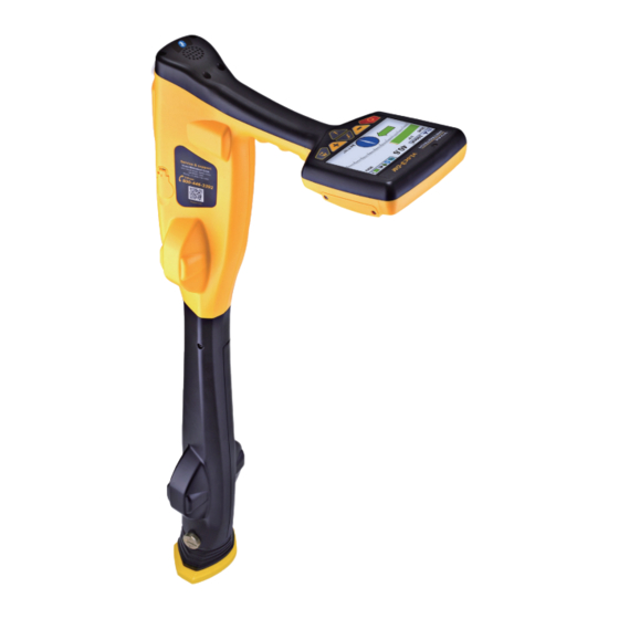
Page 16: Vloc3-Dm Receiver Functions And Operations
The device at the bottom of the locator tube is the DM low-frequency sensor foot. This device is used to detect the low- frequency component (frequencies between 3Hz and 8Hz). These are the vLoc3-DM current mapping frequencies. When the low-frequency mapping is not required, for instance, if the equipment is being used for pipeline locating but not defect mapping, the DM foot can be removed. -
Page 17: Removing The Dm Low-Frequency Sensor Foot
When setting the retaining screw on the side of the antenna tube, hand tighten only. Charging the Receiver Batteries The vLoc3-DM can be used with either alkaline batteries or an interchangeable rechargeable battery pack. The central illuminated section within the battery icon indicates the amount of charge remaining. - Page 18 Receiver Functions and Operations Connect the charger to the charging/accessory socket of the receiver. Connect the charger to the mains and switch on. The LED indicator on the charger will illuminate red until the batteries are fully charged, at which time the LED will change to green.
-
Page 19: Vloc3-Dm Receiver Main Display (Locate Screen)
Receiver Functions and Operations vLoc3-DM Receiver Main Display (Locate Screen) Locate frequency Left/Right locate arrows Distance from last recorded reading (requires GPS option active) Compass Line direction indicator 69.9 419mA ’ ’’ 25dB 98Hz Left/Right arrows Locate signal bar graph: Green indicates low distortion, Blue indicates minor distortion, and Red indicates excessive distortion. -
Page 20: User Menu
Receiver Functions and Operations When in the graphing Mode/Screen the soft key operated by the key has the following functions as indicated by the changing icon: Softkey icon in Graph mode Function Scales the horizontal axis Scales the vertical axis... - Page 21 New Survey Main Menu Note that the manual shows four screens, but only one is shown on the vLoc3-DM display at a time. Note that where you see this sign , it means that pressing the enter button gives access to the sub-menu associated with this button.
- Page 22 The DM Current Warning feature is enabled or disabled using the app “MyLocator3”. Pipe Diameter - The vLoc3-DM receiver measures the distance to the center of the pipe. If the pipe diameter is entered, the depth indicated will be the depth to the top of the pipe i.e. the depth of cover.
- Page 23 Internal - The vLoc3-DM has an internal GPS module installed as standard. This is a low accuracy, typically +/-3m. Bluetooth - If the Blue tooth option is selected, the vLoc3-DM can be paired by Bluetooth with a more accurate GPS system.
-
Page 24: Self-Test
If the unit fails the test, try again in a more interference-free area. If it continues to fail, return the unit to Vivax-Metrotech or one of its approved repair centers for investigation and repair. Note that the vLoc3-DM foot is not tested during the self-test. To test this item, use the unit over a known pipe and check measured values fall within the published specification. ... -
Page 25: Dm Current Warning
Receiver Functions and Operations 4.8.1 DM current warning It only appears in the Info screen when the current change exceeds a pre-determined value. 4.8.2 Signal Overload This a very unusual situation and is usually caused by operating very close to a power transformer or placing the unit very close to a transmitter in the Induction mode. -
Page 26: Classic Locating Modes (Response)
Receiver Functions and Operations 4.10 Classic Locating Modes (Response) The vLoc3-DM receiver has an array of six antennas, and these can be toggled through different configurations (modes) to provide different responses to the signals radiating from buried utilities. The modes are: 4.10.1 Peak Response Mode Two horizontal antennas provide a “Peak” or maximum signal response over the center of the buried line. The compass (line direction indicator) aligns itself parallel to the direction of the cable (available in Active modes). -
Page 27: Peak With Arrows Response Mode
Alternative Locate Screens As previously mentioned, the vLoc3-DM has a number of alternative screens. The following section describes the operation of these screens. It is left to the user to decide which is the best screen for a particular application. - Page 28 Receiver Functions and Operations Using the Vector screen 1. Apply the signal to the target line in the usual way and select the vector screen by using long presses on the “return” button until the desired screen appears. 2. Position the locator within the approximate position of the target line. Use the plan view to help guide you towards the target line.
- Page 29 Receiver Functions and Operations 64.6mA 61.3mA 0.00m 0.00m 1.08mA 98Hz 1.05m 98Hz The depth and current readings Frequency selected Target line Lines of confidence (closer these are to the target line indicates more confidence) Arrow indicates the direction to move towards the line. It will only show when the distance to the target line is far away.
- Page 30 Receiver Functions and Operations 5. As long as the locator is detecting a valid signal, the depth (or locate current) will be available regardless of locator orientation, i.e. the locator does not need to be aligned with the target line in the forward back orientation. It is recommended that, in this mode, ...
-
Page 31: Using The Vloc3-Dm Receiver
Using the vLoc3-DM Receiver 5. Using the vLoc3-DM Receiver Locating a Pipeline NOTE There are a number of antenna configurations available, and each has a particular response. However, for the purposes of simplicity, the method below uses the generic “peak with left-right arrows.”... -
Page 32: Taking Depth And Current Readings (Information Screen)
Using the vLoc3-DM Receiver 13.5 80.8mA 11dB 0.27m 98Hz 0.00m NOTE The largest signal and current reading will probably be generated by the anode bed cable. Confirm which is which by taking DM current readings and noting the current direction. The currents on the pipe will be flowing toward the transmitter. -
Page 33: Storing The Results
Deleting logs..Are you sure? Graphing results on the screen The vLoc3-DM has an onscreen graphing facility. Access to this facility is through the info screen. Press the “enter” key when in the “Info” screen. 0.75m 59’55.95961’’N 27.50m... -
Page 34: The Walk-Back Feature
Using the vLoc3-DM Receiver When in the graphing mode/screen the soft key operated by the key has the following functions as indicated by the changing icon: Softkey icon in Graph mode Function Shifts the horizontal axis, use the left and right soft keys to shift the horizontal axis. -
Page 35: Signal Direction Precision Identification
Greater than 50m from measurement Signal Direction Precision Identification (Available for vLoc3-DM with SD activated) Some models in the vLoc series of locators contain a feature called “Signal Direction”. This feature is used to verify if the line being located is the target to which the transmitter has been connected. - Page 36 Using the vLoc3-DM Receiver To synchronize the receiver to the transmitter at the beginning of a survey, pinpoint the pipe very close to the transmitter, be sure that it is the correct line. Then, standing facing away from where the transmitter is attached, press the “i” pushbutton. The unit will now display the information screen showing the depth of line, signal current, and an “SD”...
-
Page 37: Using The A-Frame Fault Finder
The A-frame is used to pinpoint coating defects along the pipeline. It does this by measuring the voltage in the ground caused by the vLoc3-DM signal current entering the pipe at a fault. It is necessary to make a physical/electrical contact with the ground. The A-frame has two spikes to facilitate this. -
Page 38: Fault Finding Method
A-frame Defect Note that the receiver is not shown so as to simplify the diagrams. In all diagrams, the vLoc3-DM receiver would be connected. Continue walking in the direction of the arrow, placing the A-frame in the ground at approximately one-meter intervals saving the results as you go. -
Page 39: Using The A-Frame Where There Are Many Defects Such As Porous Coating
Using the vLoc3-DM Receiver Sometimes it is not possible to gain access to the pipe position. If this is the case walking along the route of the pipe a few meters to one side can very often produce good results. This procedure is also useful where the pipe runs under “blacktop,”... - Page 40 Using the vLoc3-DM Receiver Two methods are available, both enable simultaneous ACVG and Current gradient mapping. To take a DM current reading when in the A-Frame mode, press the “Info” key. If in simultaneous mode the following will be displayed: 1.18m...
-
Page 41: Using External Gps
• Switch on the external device. • Switch on the vLoc3-DM and enter the User setup menu by a long press on the “i” button. • Use the “+” and “-” keys to scroll down to the option “Bluetooth Pairing”. -
Page 42: Transferring Data From The Locator To A Computer
(see previous section on Bluetooth devices). Once paired with an external device, the vLoc3-DM will await valid GPS data from the external device. The GPS icon will turn green when a valid GPS signal is detected. This can take from a few seconds to a few minutes depending on the device and whether it is doing a “cold”... -
Page 43: Updates Page
The “Update From Disc” feature will only be available if a suitable dongle is also attached to the PC. This feature allows the user to install older versions of firmware stored on the computer, although it is advised that only the latest version of firmware is used. 6.4.3 Toolbar The vLoc3-DM locator can be configured so that features can be switched on or off. This enables the user to tailor the instrument to meet the needs of their application while keeping the user interface uncluttered. The toolbar at the top of the screen enables the user to create configurations. The application toolbar looks like this: ™... -
Page 44: Data Logging
This will open an existing configuration file This will read the configuration from the (*.vmcfg). connected locator. This will save the configuration to a file. Icon not Active for vLoc3-DM. This will write the configuration to the This will display information about MyLocator3. connected locator. 6.4.4 Data Logging Clicking on the Data Logging tab will display information about the state of the attached locator’s data log contents. -
Page 45: Splash Screen
Using External GPS 6.4.5 Splash Screen On this page, an image can be loaded which can be used as a splash screen by the locator when it is switched on. The locator has an LCD screen with a resolution of 480 by 272 pixels. The image loaded into MyLocator3 will be scaled to fit the width of the screen. If the scaled image height is less than the LCD height, then the image is centered vertically and white bars are used as padding. -
Page 46: Menu Settings
Using External GPS The “Frequencies” page will allow the user to refine which frequency modes are available when the locator F-key is pressed and which frequencies appear on the locator menu. 6.4.7 Menu Settings The “Menu Settings” page allows the user control over which menu items appear on the locator and also the initial setting of the menu item when the locator is first used after configuration. The menu items with a right pointing arrow can be expanded to reveal further sub-menu items. -
Page 47: Interpreting Results
The locator must be aligned and held vertically. The measurements are only as good as the care taken to obtain them. The sensors used to detect the low-frequency vLoc3-DM profiling signal are very sensitive to low frequencies. Moving the instrument whilst the unit is calculating the information will cause the strong earth’s magnetic field to induce an interfering signal ... -
Page 48: Checking For Distorted Fields
For best results, the cross bonding should be disconnected for the duration of the survey. • Passing Vehicles The sensing devices used to detect the 3Hz vLoc3-DM profiling signal are very sensitive to low frequencies. Vehicles passing very close to the receiver will disturb the earth’s magnetic field and cause distortion of the received signal. Try to take measurements when there is a gap in passing vehicles. -
Page 49: Viewing Data
Interpreting Results Viewing Data Upload the data from the vLoc3-DM receiver as described previously in section Upload Data Files. Files can be saved in .txt, .kml, or .shp formats. 7.3.1 Viewing. xls Files Open an Excel spreadsheet and open the desired file. Something similar to the screen below will be displayed. The data is now in the form of an Excel spreadsheet and can be manipulated to create suitable graphs. -
Page 50: Viewing .Kml Files
Interpreting Results 7.3.2 Viewing .kml Files To view .kml files, it is necessary to have Google Earth installed on the host computer. If not already done, please visit the Google Earth Web and install the latest version. To launch a .kml file, double click on the selected file. If connected to the web and if Google Earth application is installed on the host computer, Google Earth will automatically launch and will zoom to the site location. Pins will indicate survey points. Clicking on a point will show measurement details for that point. (note these details are continually under review and may change without notice) The map is a typical representation, but note that this feature is under continual development and may change to include new features without notice. - Page 51 Interpreting Results In either case it is important to look at the trend of the graph rather than individual points. This is because the signals radiating from a pipe can be affected by many external influences such as: • passing cars • ground currents from stray currents • ground currents from the transmitter •...
-
Page 52: Care And Maintenance
Always dry the equipment before storing it. Checking Functionality The vLoc3-DM system can be checked using a simple test procedure. It requires an area clear of pipes and cables and free from metallic structures such as metal tanks, metal railings, and reinforced concrete. -
Page 53: Glossary
Glossary 9. Glossary Active Locate A locate where a transmitter is used to apply a signal to a buried pipe or cable, the position of which is then located by a receiver tuned to the same frequency. Active Signal A signal applied by the locator transmitter to a buried line. Typical, this is a very precise frequency. Attenuation The reduction of an electromagnetic signal from a pipe or cable. - Page 54 Notes: Vivax-Metrotech Corporation 3251 Olcott Street, Santa Clara, CA 95054, USA Toll Free: (800) 446-3392 Phone: +1 (408) 734-1400 Website: www.vivax-metrotech.com ™...
Need help?
Do you have a question about the vLoc3-DM and is the answer not in the manual?
Questions and answers