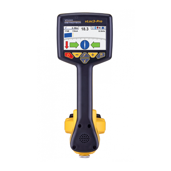
Vivax Metrotech vLoc3-Pro Training
Locator training with transmitters
Hide thumbs
Also See for vLoc3-Pro:
- User handbook manual (88 pages) ,
- Quick manual (2 pages) ,
- Quick manual (2 pages)


Need help?
Do you have a question about the vLoc3-Pro and is the answer not in the manual?
Questions and answers