
Related Manuals for Reflex servitec


Summary of Contents for Reflex servitec
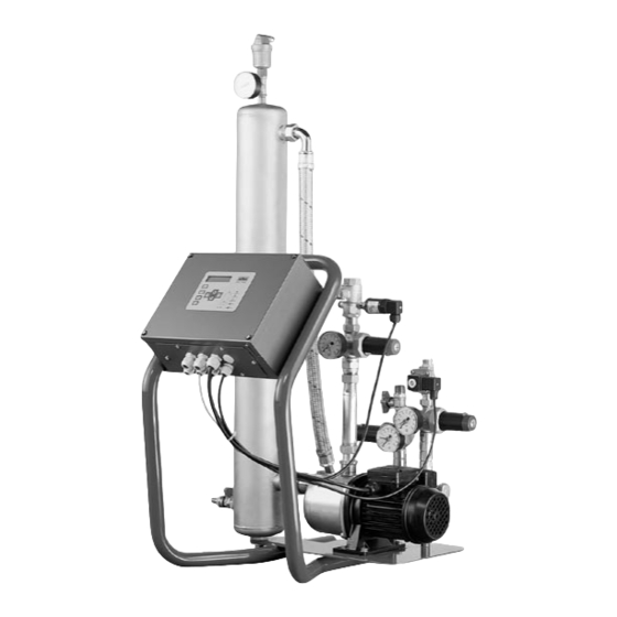
- Page 1 ’servitec’ Vacuum spray-tube deaerator Installation, operating and maintenance instructions Status 09/04...
-
Page 2: Table Of Contents
16 – 17 Service menu Summer operation Default settings Interface RS-485 Messages Maintenance Maintenance instrucitions Disassembly Periodic check-ups Reflex service General description Operation 22 – 23 Operating parameters Dimensions, weights Applications Electrical details Declaration of conformity Installation, maintenance and commissioning certificate... -
Page 3: General
19 Vacuum gauge 20 Vacuum spray-tube 21 Filling and draining ball valve Type key servitec magcontrol / 60 / gl gl - version for water glycol mixtures up to 50% glycol component Pump size Type: magcontrol - with pressure expansion vessels... -
Page 4: Operating Panel
’servitec’ General LC Display Message line Display of the active deaeration program and dis- play of messages Pressure display (only with ’servitec magcontrol’) Display of current system pressure, flashes upon pressure fault Operating mode Function LED's buttons Manual mode... -
Page 5: Safety Instructions, Regulations And Standards
An approved inspection body must be notified of necessary tests before operation (only for ’servitec’ special systems, PS x V > 50 bar x litre) and after major changes in the installation, as well as of periodic inspections. For recommended inspection intervals, see section “Periodic Inspection”. Only vacuum spray-tubes without visible external damage to the pressure body may be installed and operated. -
Page 6: Installation
0.03 A Installation − Remove ’servitec’ from the pallet and transport to the place of installation, ensuring that the ’servitec’ is carried by the frame. − When aligning the control unit ensure that the valves and feed facilities of the connection lines can be operated. -
Page 7: Installation Diagrams
− connect ’servitec’ with the system piping. The maximum permissible media temperature at the connection point is 70 °C (’servitec .../90 °C’ are applicable up to 90 °C), which is why it is installed in the system return in the case of heating systems. - Page 8 ’servitec’ Installation reflex ’servitec’ deaeration stations solve „gas problems“ in three ways: no direct drawing in of air through controlled pressure maintenance no circulation problems through free bubbles in the circuit water reduction of corrosion risk through oxygen withdrawal from the filling and make-up water reflex ’servitec magcontrol’...
-
Page 9: Electrical Connection
Remarks Feed X0 / 1 - wiring on the terminal block next to the fuses (230 V) X0 / 2 - ’servitec’ is ready cabled with earthing plug X0 / 3 Feed X0 / 1 (400 V) X0 / 2... -
Page 10: Prerequisite For Start-Up
– The system has been connected to the electrical mains system according to the applicable VDE and local EVU regulations. We recommend that you have the following operations and the induction of the operating personnel carried out by your Reflex service (→ p. 21, chargeable service according to the applicable gross price list). -
Page 11: Initial Start-Up
The starting routine commences when the control is switched on for the first time. It serves for the setting of the parameters required for the operation of ’servitec’. Should you have entered an incorrect value you can restart the starting routine by pressing the „quit“ button. -
Page 12: Filling And Bleeding The Pump
Repeatbleeding as required. Vacuum test Careful with high temperatures! Observe general safety instructions (→p. 5)! Perform the vacuum test conscientiously to guarantee the operation of the ’servitec’! – Close ball valve (6), ball valve (1) of the pump line is open ... -
Page 13: Hydraulic Balancing
Automatic mode Note: 1.7 bar For the automatic mode of the 'servitec' it must be ensured that pressure mainte- nance of the system is operational and hydraulically connected with the ’servitec’! Permanent degas. The system must have been roughly bled beforehand. Hydraulic balancing must have been completed! Display (→... -
Page 14: Cleaning Dirt Traps
After expiry of the set permanent deaeration period, clean the dirt traps of the pressure reducing valves (5, 8) of the make-up and overflow lines (not part of reflex commissio- ning!). Do not forget dirt traps (for instance ’fillset’ item F) installed by customer. -
Page 15: Operation
010 h This type of operation primarily serves for hydraulic balancing of the pressure-reducing Display (→ p. 4) ’servitec level- valve (5) (→ p. 12). However, with ’servitec magcontrol’ it is also possible to fill the sys- control’ flashes with make- tem. -
Page 16: Customermenu
General The customer menu serves to enter and change the most important ’servitec’ operating para- meters. In part, these were already processed within the starting routine during initial start-up. Additional parameter changes are possible here. Press the „menu“ button to get to the cus- tomer menu. -
Page 17: Service Menu
Only when a contact water meter is used stop (plugging jumper → p. 10) Service menu A password-protected service level is installed in ’servitec’ controls, in which additional data can be changed. This is only possible by the Reflex service, telephone +49 23 82 / 70 69-550. -
Page 18: Summer Operation
If the circulating pumps of the system are taken out of service during summer, deaeration of the mains content water can only be safeguarded if the shut-off between overflow line and pump line of the ’servitec’ is closed. If this cannot be ensured, the deaeration program should be set to make-up deaeration by way of the customer menu (→... -
Page 19: Messages
Power failure – – Check power supply Stop > 4 h – ’servitec’ has been in stop mode for – Activate auto mode as applicable more than 4 h Max. make-up quantity – The maximum make-up quantity set in –... -
Page 20: Maintenance
Caution! Observe general safety instructions (→ p. 5)! The ’servitec’ must be maintained annually, but at least after 16.000 deaeration cycles (this corresponds to a continuous dea- eration time of approximately 14 days or a continuous deaeration time of 7 days + 1 year intermittent deaeration with standard setting). -
Page 21: Disassembly
’servitec’ Maintenance / Reflex service Disassembly Before periodic inspection or disassembly of the ’servitec’ system and or pressurized parts these have to be depressurized. close ball valves (1), (6) of the control unit and (G) of the ’fillset’, open ball valve (21) until spray-tube (20) is depressurized, drain spray-tube through ball valve (21) completely, if necessary ventilation through screw-off of dipstick tube-deaeration unit (18). -
Page 22: General Description
General description Operation General description ’servitec’ is a deaeration and make-up station. It can be used in a wide range of system conditions. The main field of application are heating and cooling circuits and wherever air problems interfere with systems in form of dissolved or free gases. -
Page 23: Operating Parameters
General description Make-up ’servitec magcontrol’ With the ’servitec magcontrol’, the pressure in the heating or cooling system is registered and monitored with the help of the pressure measuring transducer (2). If the filling pressure drops below p + 0.1 bar, make-up deaeration is activated until + 0.3 bar has been reached. -
Page 24: Declaration Of Conformity
Declaration of conformity for ’servitec’ control units The manufacturer herewith confirms that the design, manufacture and testing of the ’servitec’ controls conforms with the requirements of the guideline of the council for the co-ordination of the legal requirements of the member states concer- ning electromagnetic compatibility and the low voltage guideline 89/336 EEC and 73/23 EEC. -
Page 25: Installation, Maintenance And Commissioning Certificate
Montage- und Inbetriebnahmebescheinigung Installation and commissioning certificate Die ’servitec’ wurde entsprechend der Reflex Montage-, Betriebs- und Wartungsanleitung montiert und in Betrieb genom- men. Die Einstellung der Steuerung entspricht den örtlichen Verhältnissen. Hinweis: Falls werksseitig eingestellte Werte verändert werden, so ist dies auf dem Typenschild (Mindestbetriebs- druck, SV-Ansprechdruck) bzw. - Page 26 Reflex Winkelmann GmbH + Co. KG Gersteinstraße 19 59227 Ahlen Germany Telefon: +49 23 82 / 70 69-0 Telefax: +49 23 82 / 70 69-558 www.reflex.de...
Need help?
Do you have a question about the servitec and is the answer not in the manual?
Questions and answers