Table of Contents
Advertisement
Advertisement
Table of Contents

Related Manuals for Samyung ENC SRG-150DN

Summary of Contents for Samyung ENC SRG-150DN
- Page 1 INSTRUCTION MANUAL MF/HF SSB RADIO EQUIPMENT SRG-150DN/SRG-250DN...
- Page 2 Warning RF Exposure Warning : ※ The radiated output power of this device is below the FCC radio frequency exposure limits. Nevertheless, the device should be used in such a manner that the potential for human contact during normal operation is minimized. In order to avoid the possibility of exceeding the FCC radio frequency exposure limit, human proximity to the antenna should not be less than 142 cm during normal...
-
Page 3: Table Of Contents
CONTENTS CHAPTER 1. HOW TO OPERATE THE MAIN UNIT ..............5 SET MMSI(MARITIME MOBILE SERVICE IDENTITY) ID ..............5 SSB MODE ................................5 DSC MODE ................................6 DISTRESS TRANSMISSION ........................... 8 HOW TO USE SN-100 NBDP TERMINAL ....................8 CHAPTER 2. OVERVIEW ........................10 CHARACTERISTIC ............................ - Page 4 DSC MESSAGE ..............................37 DSC DISTRESS SCREEN COMPOSITION ....................38 CHAPTER 8. DSC DISTRESS OPERATION ..................41 8-1 DISTRESS ALERT (DISATER ALERT) HOW TO SEND................41 RECEPTION OF DISTRESS ALERT (DISATER WARNING) ............... 47 THE WAY TO SEND A DISTRESS RELAY INSTEAD OF SHIP IN A DISASTER ......50 DISTRESS CANCEL SENDING A CANCEL MESSAGE ...............
- Page 5 FUNCTION DIAGRAM OF REAR SIDE .................... 102 12-6 CHAPTER 1 . TROUBLE SHOOTING .................... 103 13-1 OVERVIEW ................................. 103 13-2 MEASUREING INTRUMENT ........................103 13-3 MAINTENANCE OF SRG-150DN/250DN ..................... 103 13-4 NBDP SN-100 ..............................105 13-5 SIMPLE MODULATION OF MODULATOR ................... 106 13-6 CAUTION ................................106...
-
Page 6: Chapter 1. How To Operate The Main Unit
CHAPTER 1. HOW TO OPERATE THE MAIN UNIT SET MMSI(MARITIME MOBILE SERVICE IDENTITY) ID Press POWER key to turn on the power of the main unit and it will be changed to the following setting mode from the initial screen, as below. ➜... -
Page 7: Dsc Mode
2) Press the key repeatedly to select CH ➜ Input the desired channel with numeric buttons and then press 1-2-2 FREQUENCY SELECTION 1) Press on the front panel of keyboard repeatedly and select [TX]. Input the desired frequency with numeric buttons and press 2) Press on the front panel of keyboard repeatedly and select [RX]. - Page 8 ➜ After setting the mode to ➜ Rotate the channel dial to select the desired channel. FREQUENCY INPUT 1-3-2 ➜ After setting the mode ➜ Rotate the channel ➜ dial to move to the channel, in which there is no input of frequency ➜ Repeatedly press on the front panel of keyboard and select [TX].
-
Page 9: Distress Transmission
1-4 DISTRESS TRANSMISSION TRANSMIT A SIGNAL (DISTRESS) BY 1-4-1 EMERGENCY TRANSMISSION KEY 1) Press the KEY and hold on for 5 seconds to transmit a signal. 2) In case, if there is no response, transmit again from the 1 channel to the 6 channel after approximately 4 minutes 30 seconds (4 minutes ~ 5 minutes). - Page 10 Press [F2] and if you select [ARQ], you can be connected by ARQ MODE to the other station with the current setting channel. FEC MODE 1-5-4 Press [F2] and if you select [FEC], you can be connected by FEC MODE to the other station with the current setting channel.
-
Page 11: Chapter 2. Overview
(NBDP) and used for digitized information communication suitable for automatic processing in distress, safety and general situations. SN-100 is used when connected to the transceiver (SRG-150DN / 250DN) and outputs sub- carrier signal through the transceiver (SRG-150DN / 250DN) to transmit (Narrow band of direct printing) NBDP DATA, directly demodulates the received signal (RX) from the antenna and DISPLAYs the information through the LCD on the front side of the terminal. - Page 12 EQUIPMENT CONFIGURATION 2-1-4 Because SRG-150DN/ 250DN consists of one device, it does not require a large space for operation. SN-100 terminal is also a single device, therefore can be installed and used only by connecting cable with SRG-150DN/250DN.
-
Page 13: Equipment Components
EQUIPMENT COMPONENTS This unit consists of SRG-150DN / 250DN and SN-100 (NBDP terminal equipment). Each device is composed of functional PCB and divided into basic components and optional components. << SRG-150DN basic components >> NAME TYPE QUANTITY NOTES MF/HF-DSC transmitter/... - Page 14 Automatic Antenna SAT-100 Tuner material included) HAND MIC SM-1150 SSB-A-C Accessory 1SET SRG-2050D-PC User, SRG-150DN/250DN(ENG) Installation Manual << SRG-150DN/250DN optional components >> NAME TYPE QUANTITY NOTES Emergency Lamp EMG-Light External Speaker SS-10W4 POWER SUPPLY SP-1250ADC Domestic (including NBDP terminal SN-100...
-
Page 15: Chapter 3. Regulation
CHAPTER 3. REGULATION 3-1 GENERAL SPECIFICATIONS ※ This equipment has been tested in accordance with the IMO guideline for GMDSS. 1) Power supply DC 24V(BAT) : -10% ~ +30% , Power: 1200VA Hazardous voltage indication Insulation resistance measurement: must be higher than 1MΩ. 2) Consumption current: DC24V±15% 2.5A when receiving, 30A (MAX) when transmitting 3) Compass safety distance... -
Page 16: Transmitter Specifications
7) Dimensions (mm) SRG-150DN / 250DN: 324 (W) X 170 (H) X 347 (D) SN-100: 300 (W) X 255 (H) X 127 (D) 8) Weight SRG-150DN / 250DN about 8.1Kg SN-100 about 5Kg SAT-100 DIR 3.4Kg TRANSMITTER SPECIFICATIONS 1) Type of emission: J3E, FIB 2) Communication method: SIMPLEX and SEMI DUPLEX method 3) Frequency range: 1.605MHz ~ 27.499MHz, 10Hz STEP... -
Page 17: Receiver Specifications
13) Total Distortion and Noise: more than 20dB 14) Output Impedance: 50ohm 15) Low frequency input: + 10dB / -35dB, IMPEDANCE 600 ohm RECEIVER SPECIFICATIONS 1) Type of emission: J3E (USB), F1B (FSK) 2) Reception method: UP CONVERSION Double super-heterodyne method using phase LOCK type DIGITAL frequency SYNTHESIZER. -
Page 18: Dsc (Digital Selective Call) W/K Receiver
11) Image interference ratio: more than 70dB 12) Intermediate frequency interference ratio: more than 80dB 13) SPURIOUS RESPONSE: more than 70dB In case of DSC, NBDP when a wanted signal of 10 ㎶ and a 31.6 ㎷ unwanted signal(excluding the range within 750Hz of the wanted signal) whose range of IF it's three times that of the wanted signal, the symbol error rate is less than 1 x 10⁻². -
Page 19: Digital Selective Call (Dsc)
1) Control items: MF / HF Transceiver, DSC, WATCH-KEEPING Receiver, selection of transmitting and receiving frequencies 2) DISTRESS: 2187.5, 4207.5, 6312, 8414.5, 12577, 16804.5kHz sending alarm signal 3) Others: DISPLAY unit, remote interface, NBDP terminal, ATU BOX, ALARM BOX, HAND MIC, DIMMER, etc. 4) MAIN PROCESSOR: ADSTARD16MF512, ATMEGA64L 5) EEPROM: 24LC256 6) Display: 5 inch color LCD (800 * 480) -
Page 20: Printer (Hp-283)
CFEC (Collective Forward ERROR Correction) SFEC (Selective Forward ERROR Correction) 4) Status Display: POWER ON, STAND-BY, CALLED, CALLING, FREE, SIGNAL, ARQ, CFEC, SFEC, SEND, RECEIVER, PHASING, REPHASING, REPEAT, ERR, etc. 5) Code: 7 units CODE 4B / 3Y (B: 1785 Hz, Y: 1615 Hz) 6) Memory capacity: 16M 7) SYSTEM PARAMETER: PROGRAMING OPERATOR DATA TO FLASH DISK AND keeping as BACK UP. -
Page 21: Printer (Jp-3750)
⁃ Type number: TP411-28CL(TP-411L) ⁃ Width: 112mm ⁃ Roll diameter: 48mm ⁃ Roll length: about 28m PRINTER (JP-3750) 1) Printer specifications ⁃ Output speed: 480CPS(12CPI standard) ⁃ Resolution: 180DPI ⁃ Printing Colums: 80 Columns ⁃ Buffer: 128K ⁃ Head life: 4 billion dots ⁃... -
Page 22: Chapter 5 Front Panel
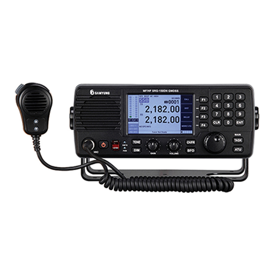
CHAPTER 4 FRONT PANEL 4-1 EXPLANATION OF KEY, KNOB AND LAMP OF THE MAIN UNIT < SRG-150DN/250DN front panel of the main unit> ① KEY PANEL ② Front display (LCD) - indicates mode / frequency / channel / use of other functions and etc. - Page 23 Adjust the brightness of the LCD BAK LIGHT (internal light) to 6 levels of 2 types. Select frequency and channel. Adjust the intelligibility (adjustment to receive the received signal clearly) It is the key that the user presses when he wants to match the antenna. It is an execution key such as item selection from the menu, input expansion and etc.
-
Page 24: Liquid Crystal Display
You can choose. : You can start and end channel / frequency scans. : It is a function to confirm ATU Manual and ATU Version. : Remote mode can be turned ON / OFF. You can choose. : The squelch can be turned ON / OFF. : Equipment SETUP function. - Page 25 If ON : There is a "beep" sound during keyboard operation. If OFF : There is no "beep" sound during keyboard operation. ⓒ HIGH : Displays the transmission output. HIGH : SRG-150DN (J3E:150W, FIB:100W) SRG-250DN (J3E:250W, FIB:150W) MID : SRG-150DN/250DN (J3E:100W, F1B:100W) LOW : SRG-150DN/250DN (J3E:50W, F1B:75W) ⓓ...
-
Page 26: Screen Lcd
ⓜ ATT-OFF : The degree of attenuation of the attenuator at the receiving end is displayed. Press keys to change to change to ATT-OFF, ATT-1, ➜ ATT-2, and ATT-3. ⓝ NB-OFF : Set up the Noise Blanker function. Press keys to change to NB-OFF, NB-ON. ➜... - Page 27 MAIN MENU 1. TUNING CLEAR 2. CHANNEL CLEAR 3. DATA-TIME SET 4. SPEAKER : ON 5. KEY TONE : ON 6. TX METER SET : VF/IC 7. AUTO TUNE 8. SELF TEST 9. M:01.00, C:01.00, D:08.03, WK:01.2 ※ *** Only Receive Function ※...
-
Page 28: Chapter6. Ssb Wireless Telephone (Tel) Mode
CHAPTER5. SSB WIRELESS TELEPHONE (TEL) MODE SSB MODE On the front PANEL ➜ Use to set to mode as follows. If you turn the front channel dial, the CH is converted, and you can press , put it on the RX, press , select the frequency you want to change to and change it from 10Hz to 10MHz with the dial. - Page 29 ⓐ It is a menu to determine the channel or frequency to scan. Select [ 1.Scan Type Set] ➜ Press the key and Freq / Ch are alternately switched. ⓑ [4.Scan Start] ➜ If you choose , the selected SCAN Type proceeds.
- Page 30 SCAN FREQUENCY SET 5-2-3 : Set the setting value in case of scanning frequency. ➜ Choose the [3. Scan Frequency Set] ➜ The following screen appears. Move to the relevant function ➜ setting ➜ [Numeric buttons] Enter the relevant values ➜ [Start]: Set the start frequency of the frequency scan.
- Page 31 2. SQL Delay: This is menu, which sets the SQL time setting value. Setting range: 1 to 20 , (1: 0050ms , 20 : 1000ms ) 3. Stop SQL: Turn SQL ON/OFF. Press to return to the main screen. LCD CONTRAST SET 5-2-5 If you click on the front keyboard window, the following window appears.
- Page 32 MANUAL TUNING 5-2-7 [1.ATU Manual Tuning] ➜ If you press ➜ ➜ , the following window appears. 2) [Note] It is recommended to not operate this menu because it is a menu that requires special knowledge. If you enter wrong value, equipment may be damaged. 3) It is possible to confirm and set the selected status of the components inside the antenna matching device.
- Page 33 1) [1.Tuning Clear]: It is menu to delete all memorized tuning data. [1.TUNING CLEAR] ➜ If you press , the following screen appears. Press to delete all memorized tuning data. Press to return to the SYSTEM SETUP screen. 2) [2.SSB-CH Clear]: It is menu to delete SSB channel data and set basic channel. [2.CHANNEL CLEAR] ➜...
- Page 34 ※ It is displayed as UTC (Universal Time Coordinated) when inputting GPS external data 4) [4.SPEAKER]: You can set the speaker sound. [4.SPEAKER: ON] ➜ ➜ Press to turn speaker sound ON / OFF. 5) [5.Key Tone]: You can turn the keyboard sound ON / OFF. [5.KEY TONE: ON] ➜...
-
Page 35: Additional Functions (Itu Channel, Rcv, Am, Dsc Mode, Etc.)
Press to return to the initial screen. 8) [8.SELF TEST] [8.SELF TEST] ➜ If you press , the following screen appears. [normality] [abnormality] Press to return to the initial screen. 9) [9.M:01.00, C: 01.00, D: 08.3, WK: 01.00] [9.M:01.00, C: 01.00, D: 08.3, WK: 01.00]: MAIN, CONTROLL, DSP, W/K displays the program version. - Page 36 If you turn with the front channel dial, it will be converted into 100Hz unit. Press put on RX and press , choose frequency , to which you going to change and change the frequency from 10Hz to 10MHz with the dial. [ Ref.
- Page 37 [ Ref. ] In [AM] mode TX frequency cannot be displayed (only RX) and AGC is set automatically. DSC MODE 5-3-4 ➜ If you press , the following ➜ ➜ screen appears. If you turn with the front channel dial, press , put on RX and press , choose frequency...
-
Page 38: Chapter7. Digital Selective Calling(Dsc)
CHAPTER6. DIGITAL SELECTIVE CALLING(DSC) 6-1 OVERVIEW 1) DSC is abbreviation for Digital Selective Calling. 2) DSC uses MF / HF bands to send digital disaster and general calls to ships, configure and send station responses. 3) There are 16 call frequencies, using for the DSC distress, safety and urgency of the MF / HF bands: 2187.5 / 4207.5 / 6312.0 / 8414.5 / 12577.0 / 16804.5 Khz. -
Page 39: Dsc Distress Screen Composition
2) MMSI - The ID of the ship, the ID of the calling station, the ID of the coast station start with '00', and the GROUP ID starts with '0'. 3) PRIORITY A significant and an imminent danger and an immediate DISTRESS support demand The reception of calling station in case of very urgent... - Page 40 2) Individual Rx call - "*" indicates that the data with the error has been received. - "-" means that there is no information.
- Page 41 6-3-2 TRANSMISSION 1) DISTRESS ALERT 2) Individual Tx call...
-
Page 42: Chapter 8. Dsc Distress Operation
CHAPTER 7. DSC DISTRESS OPERATION 7-1 DISTRESS ALERT (DISATER ALERT) HOW TO SEND - The GMDSS ship is loaded with the DSC terminal, which transmits the Distress Alert to a life-threatening situation. - The coast station receives the Distress Alert and sends the Distress Alert response call to the ship in disaster. - Page 43 6) After sending all of the Distress Alert, wait for the Distress Alert response from the coast station and display "WAIT FOR ACK" on the screen. 7) If no response is received from the coast station, wait 3 minutes 30 seconds to 4 minutes 30 seconds for a Distress Alert automatic retransmission response.
- Page 44 If you press the key , the alarm window disappears and the following screen appears. 12) The elapsed time after the DISTRESS transmission is changed to the last time after receiving the Distress Alert response. MODIFY THE INFORMATION AND SEND A 7-1-2 DISTRESS ALERT.
- Page 45 2) With NATURE selected, press the ENTER key 3) Choose one of the 11 listed below and press the ENTER key. FIRE LIST ABANDON FLOOD SINK PIRACY COLLISION DISABLED OVERBOARD GROUND UNDESIGNATED 4) With GPS INPUT selected, press the ENTER key. AUTO MANUAL NOINFO...
- Page 46 Numeric key 1 is the North, 2-South input LAT : N 12 〬 34.---- LON : E --- 〬 --.---- INPUT Numeric Key If you input ENTER at this time, you cannot input below the decimal minute (point) unit LAT : N 12 〬 34.5678 LON : --- 〬...
- Page 47 SINGLE MULTI – sends the Distress Alert on 2~6 frequencies, automatically selected 2Mhz / 8Mhz and can choose 4Mhz / 6Mhz / 12Mz / 16Mhz. SINGLE - can be transmitted at the selected Distress frequency. 2/4/6/8/12 / 16Mhz, and repeats it continuously (at least one frequency must be selected).With selected frequency among 2/4/6/8/12/16Mhz ⌧...
-
Page 48: Reception Of Distress Alert (Disater Warning)
At this time, if you press the key , menu to change the used frequency appears as follows. If you choose, it will be set the same frequency as it shown in the following table in frequency of voice and Telex. In the case of telex, the frequency of the connected telex automatically changes if it is not communicating. - Page 49 RECEPTION OF DISTRESS ALERT (DISASTER 7-2-1 WARNING) IN MF BAND 1) Press to turn off the alarm and close the alarm window. 2) If there is no response call from the coast station while receiving a Distress Alert more than two times, contact the vessel, which received disaster, with radio. 3) Press , if OK is selected according to the following message, the 2M BAND Distress Alert response is transmitted immediately.
- Page 50 4) After transferring, the following screen is displayed. RECEPTION OF DISTRESS ALERT (DISASTER 7-2-2 WARNING) IN HF BAND In case when a Distress Alert is received from the HF band, a DISTRESS ALERT response can’t be send. Relay the Distress Alert in the following cases. - 1.After receiving a Distress call in case of not receiving Distress Alert response call from the coast station for 5 minutes.
-
Page 51: The Way To Send A Distress Relay Instead Of Ship In A Disaster
If 3 minutes didn’t pass, the following warning will appear. Press to enter the RELAY configuration screen, press F2 to return to the original screen. 3) If you choose INDIVIDUAL in FORMAT, you can RELAY to individual vessel 4) If you choose GEOGRAPHIC in FORMAT, you can RELAY to all the vessels in specific area. - Page 52 SEND DISTRESS RELAY TO A COAST STATION 7-3-1 1) If you press on the main screen, "DROBOSE COMPOSE" screen will be configured. DROBOSE : Distress Relay Behalf Of a Some Else 2) Leave INDIVIDUAL in Format and select the TO item. 3) If you select the TO item, the screen to select [DIRECT INPUT] / [ADDRESS BOOK] will appear.
- Page 53 SENDING A DISTRESS RELAY TO THE AREA 7-3-2 NEAR THE SHIP If the coast station instructs the Distress Relay to be sent to the area near the ship, you have to follow the procedure below. The Distress Relay shall not be transmitted unless instructed by the coast station.
-
Page 54: Distress Cancel Sending A Cancel Message
[CENTER/RAD] [CONER/DEV] Use numeric keys to input. In case if there is location input, the area within 500NM is automatically entered at the location of the charity. 4) The subsequent input is the same as the DISTRESS RELAY, which was sent to the coast station. - Page 55 2) If you press , it will be changed to the screen, where you can choose the frequency to send a Distress Cancel and the frequency to send a cancel message. At this time press and you will send a Distress Cancel call to the relevant band at the DSC frequency and a window will appear with instructions according to the corresponding communication mode.
-
Page 56: An Example Of Processing Multiple Disaster Messages
3) For sending a Distress Cancel to all bands will be used button . At this time, you can turn the knob (front channel change knob) to select a frequency and press to send a Distress Cancel call again to the corresponding DSC frequency band. - Page 57 1) DISTRESS ALARM sound 2) The alarm is completed only by manual operation. 3) The communication frequency changed to 4125.00Khz. 7-5-3 RECEIVING THE SECOND MESSAGE Message: DISTRESS ACK Received DSC frequency: 4207.5Khz 1) DISTRESS ALARM sound 2) The alarm is completed only by manual operation. 3) The communication frequency is maintained at 4125.00Khz.
- Page 58 1) DISTRESS ALARM sound 2) The alarm is completed automatically after 10 seconds. 3) The communication frequency is maintained at 4125.00Khz. 4) Input to change the communication frequency of ➜ 12290KHz. 5) Here is the following message. 7-5-5 RECEIVING THE FOURTH MESSAGE Message: DISTRESS ACK Received DSC frequency: 12577Khz 1) DISTRESS ALARM sound...
- Page 59 5) Input to select from 6 frequency bands. ➜...
-
Page 60: Chapter9. Common Dsc Message Calling And Receiving
CHAPTER8. COMMON DSC MESSAGE CALLING AND RECEIVING 8-1 INDIVIDUAL CALL The individual call calls the specified station. 8-1-1 INDIVIDUAL CALL TRANSMISSION 1) If you press of the main screen, then the "DSC CALL" screen will be configured. 2) Since the default call type of "DSC CALL" is INDIVIDUAL, there is no need to change the call type. - Page 61 If select a band, the callable DSC TX / RX frequency will be displayed and you can select one of them. 2Mhz : If it is a ship call (if MMSI does not start with 00). INT :Tx2177.0/Rx2177.0 2Mhz : If it is a coast station call (if MMSI starts with 00) INT :Tx2189.5/Rx2177.0 4MHz 6MHz...
- Page 62 LOC2 :Tx22375.5/Rx22445.0 LOC2 :Tx25209.5/Rx26122.0 - When is Safety/Urgency Priority 2187.5Khz 4207.5Khz 6312.0Khz 8414.5Khz 12577.0Khz 16804.5Khz Select the DSC frequency you want to call. 6) If you choose MODE, you can choose [TELEPHONE]/ [TLX FEC]/ [TLX ARQ]. TELEPHONE TLX FEC TLX ARQ Select COMM (communication and communication frequency) to input used communication frequency, only input of the same band as the DSC calling frequency is possible.
- Page 63 9) If you receive a response, an alarm sounds and an alarm window is displayed. If you press , the alarm window disappears and the alarm sound stops. Passed time is displayed after the response at the top-right of the screen. The communication frequency can be changed according to the type of response and it can communicate with the other station.
- Page 64 NO OPERATOR [CHANGE] – The response after changing the communication frequency at the called station, which received an Individual call. In this case, if the frequency, which cannot be used as follows, comes in the response, it does not change to the corresponding frequency.
-
Page 65: Group Call
[ACCEPT] - Respond to the communication frequency, at which was sent an Individual Call, as agreed, by pressing , it responds immediately and can be changed to the communication frequency to communicate with the other station. [REFUSE] -Reject the communication frequency, at which was sent an Individual Call, for the following reasons by pressing , its REASON ➜... - Page 66 1) If you press on the main screen, The "DSC CALL" screen is configured. 2) If you press , "TYPE" selection window is displayed, select the [GROUP]. INDIVIDUAL GROUP TEST POSITION AREA 3) If you select from the TO article, the screen to select [DIRECT INPUT] /[ADDRESS BOOK] appears.
- Page 67 RECEIVE A GROUP CALL 8-2-2 1) After changing to the DSC mode, change to the channel, at which you are going to receive, and wait for DSC reception. (GROUP call is called at the frequency, which W / K cannot receive) [3.
-
Page 68: Test Call
The alarm sound stops and the alarm window disappears. TEST CALL TEST CALL RECEIVING 8-3-1 1) Press on the main screen and the "DSC CALL" screen is configured. 2) If you press , "TYPE" selection window is displayed, if you select [TEST], it shifts into TEST call configuration screen. - Page 69 3) If you select from the TO article, the screen to select [DIRECT INPUT] / [ADDRESS BOOK] appears. [DIRECT INPUT]: Input the MMSI by directly entering the numeric key. [ADDRESS BOOK]: It is a method to input MMSI by selecting from entered names. If you select this article, you can select [SHIP STATION] / [COAST STATION] individually 4) If you select the DSC item, enter the DSC frequency you want to call.
-
Page 70: Position Call
RECEIVING A TEST CALL 8-3-2 1) Set up an auto response It is possible to set the function to respond automatically when TEST call is received. [1.DSC SETUP] ➜ [4.AUTO ACK SET] ➜ ➜ ➜ You can turn it ON in [1.AUTO ACK TEST : ON] ON. - Page 71 TRANSMISSION REQUEST CALL FOR LOCATION 8-4-1 INFORMATION 1) If you press on the main screen, "DSC CALL" is configured. 2) If you press , "TYPE" selection window is displayed. If you select [POSITION], it changes to POSITION call configuration screen. INDIVIDUAL GROUP TEST...
- Page 72 5) Press to send a POSITION call, wait for the response at transmitted frequency. 6) When a response is received, an alarm sounds and an alarm window is displayed. If you press the alarm window disappears and the alarm stops. It is displayed after the response in the upper right corner of the screen.
-
Page 73: Area Call
AREA CALL AREA CALL TRANSMISSION 8-5-1 1) If you press on the main screen, "DSC CALL" is configured. 2) If you press , "TYPE" selection window is displayed. If you select [AREA], it changes to AREA call configuration screen. INDIVIDUAL GROUP TEST POSITION... - Page 74 [CENTER/RAD] [CONER/DEV] You should use numeric keys to input. If there is a position input, the area within 500NM is automatically entered at the position of the ship. 4) When you select the DSC article, input the DSC frequency you want to call. 2187.5Khz 4207.5Khz 6312.0Khz...
-
Page 75: Dsc Test
※ To put DSC information related to MEDICAL Craft/NEUTRAL Transport in AREA call [1.DSC SETUP] ➜ Turn ON press ➜ ➜ [5.MEDICAL : ON] and you can enter if select the SUBJECT in the AREA configure screen. RECEPTION OF AREA CALL 8-5-2 1) When it is received, the alarm sounds and the settings are changed to the set communication frequency and mode in the call. - Page 76 Send the Dot pattern at 4207.50KHz. 8-6-2 MARK TRASMIT ➜ 1. DSC SETUP ➜ ➜ 9. DSC ➜ TEST ➜ ➜ 2.Mark Trasmit ➜ Send the Mark signal at 4207.50Khz. 8-6-3 SPACE TRASMIT ➜ 1. DSC SETUP ➜ ➜ 9. DSC ➜...
-
Page 77: Chapter 10. Printer
When it is raised to the upper side, the power is turned on to this unit, and the PRINTER HEAD is one round trip, pushing PRINTER paper by one row. However, the power switch of the SRG-150DN / 250DN main unit to which this unit is connected must be ON. - Page 78 In this cover, the printer paper is stored. 3) Normal operation - Check that the power of the SRG-150DN / 250DN main unit connected to this unit is turned on. - Turn the POWER switch up to turn on the power - This automatically puts the DSC MESSAGE and DATA of the transmission and reception sent from the SRG-150DN / 250DN into operation.
-
Page 79: Jp-3750 Printer
JP-3750 PRINTER 1) Normal operation ① Make sure that the power of the SRG-150DN / 250DN main unit connected to this unit is turned on ② Turn on the POWER switch and turn on the power ③ It automatically enters the DSC MESSAGE and DATA of the transmission and reception sent from the SRG-150DN / 250DN. -
Page 80: Chapter11. How To Use Sd-250(Alarm Box)
CHAPTER10. HOW TO USE SD-250(ALARM BOX) DISTRESS TRANSMITTING 10-1 1) If you press 'Distress key' (Red Button) for 3 sec., it alarms for 3 seconds. After that, the red light is turned on with bip-sound. While Distress Key is blinking, transmitting is started to work and location of disaster, time, ship's ID are sent to DSC 6 CH in order. -
Page 81: Chapter 11. Nbdp Terminal
CHAPTER 11. NBDP TERMINAL 11-1 DESCRIPTION <NBDP Unit> ① Front display (LCD) – Display channel, Transmit / receive frequency indication, VOLUME, RF.GAIN, CLARIFY, ATT, TX POWER, AGC and Function key. ② Speaker - Sounds when receiving data or receiving alarm. ③... -
Page 82: Intial Screen Of Nbdp Terminal
11-2 INTIAL SCREEN OF NBDP TERMINAL When the power switch is turned on, the initial screen is displayed as shown below. 11-2-1 INITIAL SCREEN FUNCTION DESCRIPTION Displays the call to CHANNEL and the current CHANNEL. Set the transmission frequency. Set the receive frequency. Displays RF.GAIN setting value as a graphical bar . - Page 83 11-2-2 FUNCTIONS ON THE INITIAL SCREEN BUTTON DESCRIPTION ∙ [1 Brightness] : You can adjust the backlight brightness of the LCD screen in five steps with the [F1] button. ∙ [2Connection] : The [F2] button allows you to set the Automatic Repeat request mode and the FEC mode.
- Page 84 11-3-1 SETTING TX FREQUENCY ① Press [F7] button on the keyboard. ② Input the frequency with [Number button]. [ Ref. ] ☞ While inputting frequency if press [], [], curser will move. ③ Press [ENTER] button. [ Ref. ] ☞ Available TX Frequency range: 1.605MHz ~ 27.499MHz. 11-3-2 SETTING RX FREQUENCY ①...
-
Page 85: Setting Tx/Rx Frequency [Arq] Mode
② Revert the channel you want to communicate using [],[],[],[] button. press [Enter] button. Set TX/RX frequency to registered freq. on channel displaying the first display of NBDP. 11-3-4 SETTING TX/RX FREQUENCY BY CALLING CHANNEL ① Press [F6] in Keyboard. ②... - Page 86 11-4-2 CONNECTING BY DESIGNATION OTHER STATION ① Press [F10] on the keyboard, Main Menu screen display. ② Move the cursor with []/[] button to ‘0. [ARQ]’ press[Enter] and the following screen will appear. ③ Revert the other station you want to communicate using [],[],[],[] button. press [Enter] button, the following screen will show.
- Page 87 [ Ref. ] ☞ can be back to forward display pressing [ESC] button. ④ Revert the channel you want to communicate using [],[],[],[] button, press [Enter] button. ⑤ Call the other station with selected frequency displaying next [ARQ] mode first display.
-
Page 88: Fec] Mode
※ [Left Shift] + [Space] : Covert language.(English, Russian) ☞ Caution!!) [Korean] is selected : [Korean] / [English] shift [English] is selected : [English] [Russian] is selected : [Russian] / [English] shift ④ The use of [Function] button on the initial screen of [ARQ] mode [ Ref. - Page 89 11-5-1 CONNECTING THE OTHER STATION BY SELECTIVE FECMODE 1) Communication with present selection Channel ① Press [F2] button on the keyboard and LINK MENU screen shows. ② Move the cursor to 2. [FEC] with []/[] button Press [Enter] and the following screen shows.
- Page 90 [Enter] button. ⑤ Call the other station with selected frequency displaying next [SFEC] mode first display. [ Ref. ] ☞ To stop calling, press [F8] and it will be back to Telex initial screen ⑥ If connected with other station, cursor blinks on the left top of the screen. 11-5-2 CONNECTING WITH THE OTHER STATION BY COLLECTIVE FEC MODE ①...
- Page 91 ③ Press [Esc] button and [FEC] mode initial screen shows. Indicate other station on selected channel frequency. [ Ref. ] ☞ To stop calling, press [F8], then it is changed to first display of Telex ④ When the call is connected with other station, cursor blinks on the top left of message screen.
- Page 92 [F2] : [2Hereis] – transmit answering code of your vessel (Answer back code). ⚫ [F3] : [3TMS] – transmit current time. ⚫ [F4] : [4F.send] – transmit an edited file at edit mode. (refer to ‘14-5-5 transmitting ⚫ file ) [F5] : [5Macro] –...
-
Page 93: Communication Opposite Side Country
11-6 COMMUNICATION OPPOSITE SIDE COUNTRY (COASTAL COUNTRY OR VESSEL COUNTRY) STATION EDIT AND FREQUENCY REGISTRATION ① Maine menu will be displayed by press [F10] as below. ② Move cursor by [up/down arrow key], then choose 2. Station Edit below screen will be displayed by pressing [Enter]. -
Page 94: Station Print (Opposite Side Country And Frequency Print Output)
④ Move cursor [Station input] press [Enter]. ⑤ Input [Station name] saved by pressing [Enter]. ⑥ Move cursor [ID input] press [Enter]. ⑦ Input [ID input] saved by pressing [Enter]. ⑧ Move cursor to desired Channel [Tx] press [Enter]. ⑨... -
Page 95: Registration Of Macro Command
REGISTRATION OF MACRO COMMAND 11-8 ※ Registered frequent use TXL number or abbreviation code within 20 characters. ① Below Main Menu will be displayed by pressing [F10]. ② Move cursor by [up/down arrow] to 4. Macro Command below screen will be displayed by pressing [Enter]. -
Page 96: Initial Setting Of System Set
② Move cursor by [up/down arrow] to 5. Editor below screen will be displayed by pressing [Enter]. ③ Write and edit a message and FEC, NAVTEX receive Data automatically saved. [ Ref. ] ☞ write and edit by using [function] key under the Edit message screen. ④... - Page 97 ② Move cursor [up/down arrow] to 6. System Setbelow screen will be displayed by pressing [Enter]. ③ Description of System Setting Menu ⓐ setting [0. ARQ/FEC 4- or 5-digit ID] After ‘② choose [0. ARQ/FEC 4- or 5-digit ID] [Enter] input [number key] ...
- Page 98 After ‘②’ choose [3. Collective FEC Receiving] choose [On] or [Off] by [Enter] return and saved to Main Menu by pressing [ESC]. ⓔ setting [4. Maximum FEC Error Ratio] If error rate is higher than setting value, when FEC Mode receiving, receiving will be stopped.
- Page 99 After ‘②’ choose [7. NAVTEX ID Data Clear] [Enter] NAVTEX ID Data Clear ? will appear choose Yes deleted NAVTEX broadcast ID and return to System Setting Menu by pressing [Enter]. ⓘ Setting [8. ID Printing] After ‘②’...
-
Page 100: Nbdp Test
0. Memory-data Clear : Delete the Station Name 1. Edit-File Clear : Delete the Macro Command File & Editor File 2. FEC-Recv-File Clear : Delete the received FEC-Recv-File NBDP TEST 11-11 ① Press [F10] button on the keyboard and Main Menu screen shows. ②... -
Page 101: Lcd Off
7) Freq-Shift View - After Freq-Shift Correct, this shows how well the frequency compensation is done 8) Freq-Shift Clear - Function to clear the frequency compensation. [ Ref. ] ☞ Freq-Shift Correct precaution ① Operate main unit and terminal after full warm-up ②... -
Page 102: Chapter 12. Nbdp Terminal Circuit
Finally the IF signal and BFO will create the demodulated signal on (IC3) and transfer it to T-130 board. ② The other RF signal goes through Impedance matching circuit and it is transferred to the antenna connector of (SRG-150DN/250DN) W/K. LOCAL SYNTHESIZE BOARD (T-133) 12-4 T-133 board creates 1’st (F... -
Page 103: Function Diagram Of Rear Side
If it is overpowered +32V, then power off. Prevention to reversing voltage circuit is built-in. FUNCTION DIAGRAM OF REAR SIDE 12-6 ① EMC : Supply power +24 to EMC light ② ANT IN : Impedance 50Ω MF / HF RX antenna jack. ③... -
Page 104: Chapter 1 . Trouble Shooting
5. Frequency counter that can be check 100MHz band 6. OSCILLOSCOPE that can be check 100MHz band 7. Other testers 13-3 MAINTENANCE OF SRG-150DN/250DN 1. Antenna When error of communication happens in installation and usage in terms of receiving sensitivity and noise, you need to check if there is a faulty of Antenna... - Page 105 d) After connecting the high-frequency wattmeter between this equipment and ATU, measure the progress wave and the reflected wave. If the VSWR(Voltage Standing Wave Ratio) is less than 2:1, the connection of the antenna, connectors and coaxial cable is stable and the parts have no defect. If the VSWR is more than 2:1, the connection of the antenna, connectors and coaxial cable is bad or the parts have defect.
-
Page 106: Nbdp Sn-100
LCD. When error happens, please check as follow. 1. POWER ① Power is not working. - 24V is supplied only when power supply is connected to SRG-150DN/250DN. If there is something wrong, check the power supply switch, the connector cable to SRG-150DN/250DN, fuse (5A), power polarity. -
Page 107: Simple Modulation Of Modulator
- Check if the connector is correctly connected between SRG-150DN/250DN and terminals. - Check if 1.7kHz±85Hz can come out from DM1 11 pin of T-130 PCB. - Check if the signal is supplied to SRG-150DN/250DN. 13-5 SIMPLE MODULATION OF MODULATOR As this equipment is designed to have minimum parts to adjust setting, all modulator other than the modulator for power supply should be adjusted by manufacturer if required.
Need help?
Do you have a question about the SRG-150DN and is the answer not in the manual?
Questions and answers