
Related Manuals for JENCO 6360


Summary of Contents for JENCO 6360
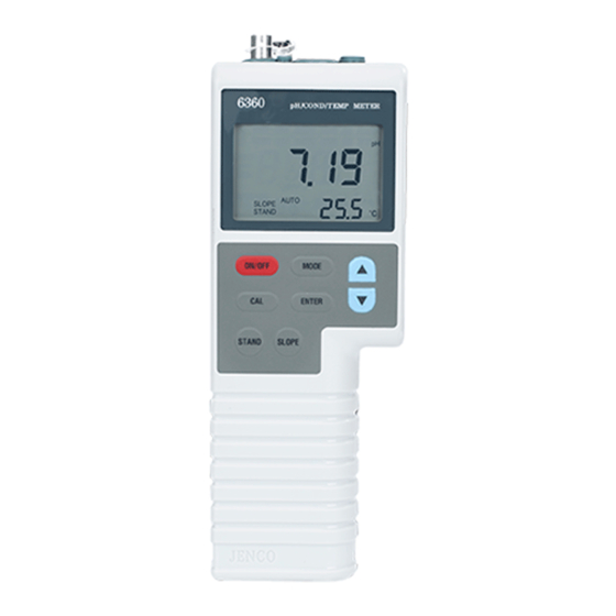
- Page 1 Operation Manual JENCO MODEL 6360 MICROCOMPUTER BASED pH/mV/Conductivity/TDS/ Salinity/Temperature PORTABLE METER 6360...
-
Page 2: Table Of Contents
CONTENTS GENERAL INTRODUCTION………………....1 INITIAL INSPECTION……...………………....2 WATER PROOF…….……...………………....2 INSTALLING THE BATTERIES..…………....3 DISPLAY & KEYS FUNCTIONS…..……………...………4 ..............4 A. Display ..............6 B. Keys OPERATIONAL PROCEDURES..……......8 ........8 A. Preparing Standard Solutions ............9 B. Calibration ........13 C. Conductivity Measurements ........13 D. Save, Recall and Delete Data. RS232C INTERFACE OPERATION...... -
Page 3: General Introduction
GENERAL INTRODUCTION Thank you for selecting the 6360 meter. The 6360 is a precision tool that measure pH, ORP, conductivity, TDS, salinity and temperature. A built-in microprocessor stores, calculates and compensates for all parameters related to conductivity and temperature determinations. -
Page 4: Initial Inspection
INITIAL INSPECTION Be careful to unpack the unit and accessories. Inspect for damages made in shipment. If any damage is found, notify your Jenco representative immediately. All packing materials should be saved until satisfactory operation is confirmed. WATER PROOF Though this unit has a waterproof IP65 case, DO NOT use it underwater. -
Page 5: Installing The Batteries
INSTALLING THE BATTERIES The 6360 meter is packaged with six AAA-size alkaline batteries or a UL/CE approved AC adapter, required for operation. To insert the batteries into the meter, follow the procedure outlined below. Figure 1: Battery compartment SIDE CLOSURE SLOT Position the meter so that the bottom part of the meter is facing up . -
Page 6: Display & Keys Functions
DISPLAY & KEYS FUNCTIONS Display Figure 2: Active LCD screen 4. %- 1. LO BAT- Displays during calibration: Low battery indicator. Indicates temperature coefficient unit. 5. Main Display Units- “pH”: pH mode unit. 2. Main Display- Display the reading of pH, “mV”: ORP mode unit. - Page 7 10. AUTO/MAN- “AUTO”: Used to indicate that a temperature sensor is attached. 7. Secondary Display- Temperature reading and “MAN”: Used to indicate that a site number. temperature sensor is not attached and the pH temperature compensation is manual. 8. WAIT/CAL- “WAIT”: Used when in pH 11.
-
Page 8: Keys
B. Keys ON/OFF- Powers on and shuts off the meter. MODE- Selects display mode. In normal operation, press this key to sequentially display pH, ORP, uncompensated conductivity, compensated conductivity, TDS, salinity, Recall and Erasing interface. In calibration mode, press this key to exit the current calibration parameter and enter into the next one. - Page 9 STAND- During pH calibration press this key will start the calibration of the OFFSET of the pH electrode. STAND Press this key with ON/OFF when the instrument is off, the unit will acknowledge by displaying “7.00” for (7.00,4.01,10.01) and “6.86” for (6.86,4.00 & 9.18) in the second interface after turning on.
-
Page 10: Operational Procedures
Here are some standard solutions the user can prepare to calibrate the probe of the model 6360. Standard solution of 14.94uS at 25℃: Accurately measure out 100ml of the 147uS standard solution as in point 4. Dilute it with 900ml of distilled water. -
Page 11: Calibration
【Pressing [STAND] and turn on when it’s off.】The 6360 will acknowledge by displaying “7.00” (7.00,4.01 & 10.01) or “6.86” (6.86,4.00 & 9.18) and the text “buf” at the first display when it’s turned on then turns to normal pH... - Page 12 0.01 pH, the waiting time (about 10 seconds) will restart. In this case: A. Change the solution. B. Stop by pressing the [MODE]. C. Wait it out until the electrode stabilizes. Once the display is locked ( the "WAIT" icon will disappear), changing the input or temperature will not change the pH display.
- Page 13 mode. The “CAL” icon appears on the LCD. Press “UP” and “DOWN” key to change the value, press “ENTER” key to save the setting and go into the next setting. If pressing “MODE” key instead of “ENTER” key, the setting will be given up and go into the next setting.
- Page 14 Temperature Coefficient 1.91 25.0 ℃ The unit uses the temperature coefficient to calculate temperature compensated conductivity. The default value is 1.91%. To change the temperature coefficient, use the “UP” and “DOWN” keys to adjust the value between 0 and 4.00%. Press “ENTER”...
-
Page 15: Conductivity Measurements
Conductivity Calibration oUer 25.0 ℃ (a) Immerse the probe in a standard of known conductivity, preferably a standard in the middle range of the solutions to be measured. Immerse the probe (at least 2” to 3” or 5~7cm from the tip) into standard solution without touching the sides of the container. - Page 16 If the “Full” icon is displayed, it means that all 50 data saving sites are used up. No new data can be saved until existing saved data are deleted. Recalling readings from memory. R C L To recall saved data, press “ENTER” key to go into the “rcl” mode.
-
Page 17: Rs232C Interface Operation
SOFTWARE A demo program written in Visual Basic® 6.0 and the source are included in the accompanying disk. Read the “Model 6360 RS232 MODBUS RTU PROTOCOL.doc” to understand the procedure used inside the demo program. -
Page 18: Error Displays And Troubleshooting
ERROR DISPLAYS AND TROUBLESHOOTING SECOND MAIN Possible cause(s) -ARY MODE [Action(s)] display display Temperature > 100.0°C OVEr or temperature probe is broken. [Replace temperature probe.] a. temperature Temperature > 100.0°C. compensated [Bring solution lower Conductivity temperature.] OVEr b. TDS [Use a temperature probe.] c. - Page 19 Cond-Cal - after Undr [Use a new standard solution.] 100.0°C pressing [Enter] [Clean/replace probe.] -5.0~ Undr ORP input < -1999 mV 100.0°C Note: If the unit still does not perform normally after the above measures are taken, call Jenco Service Department.
-
Page 20: Specifications
SPECIFICATIONS Display Range Resolution Accuracy -2.00~16.00 0.01pH ±0.01pH±1digital -1999~1999mV ±0.1% FS±1digital 0.0 to 475.0uS/cm 0.1uS/cm Conductivity 475 to 4750uS/cm 1uS/cm ±0.5% FS K=0.475 4.75 to 47.50mS/cm 0.01mS/cm 47.5 to 200.0mS/cm 0.1mS/cm Conductivity 0.00 to 99.99uS/cm 0.01uS/cm ±0.5% FS K=0.1 100.0 to 200.0uS/cm 0.1uS/cm 0.0 to 475.0 ppm 0.01 ppm... -
Page 21: Warranty
If you purchased the item from our Jenco distributors and it is under warranty, please contact them to notify us of the situation. - Page 22 4F., No. 80, Songde Rd., Xinyi Dist., Taipei City 110, Taiwan TEL: 886-2-2345-6188 FAX: 886-2-2345-6791 E-Mail: sales@jenco.com.tw Website: www.jenco.com.tw Shanghai Jenco Instruments, Ltd. 18 Wang Dong Zhong Road Sijing Town, Songjiang Shanghai, China, 201601 TEL: 86-021-5761-9599 FAX: 86-021-5761-9598 E-Mail: jencos@jenco.com.cn...
Need help?
Do you have a question about the 6360 and is the answer not in the manual?
Questions and answers