Table of Contents
Advertisement
Available languages
Available languages
Quick Links
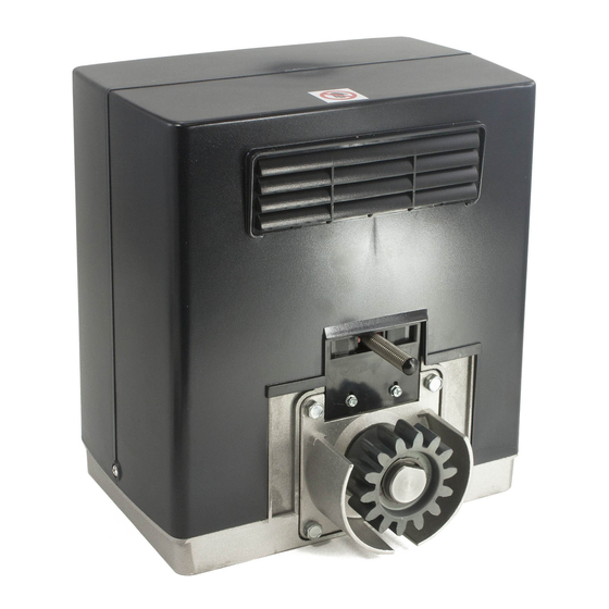
ATTUATORE IN BASSA TENSIONE PER CANCELLI SCORREVOLI A CREMAGLIERA
I
GB
LOW-VOLTAGE ACTUATOR FOR RACK SLIDING GATES
ISTRUZIONI D'USO E DI INSTALLAZIONE
INSTALLATION AND USER'S MANUAL
Via Lago di Vico, 44
36015 Schio (VI)
Tel.naz. 0445 696511
Tel.int. +39 0445 696533
Fax 0445 696522
Internet: www.bft.it
E-mail: sales@bft.it
D811419 ver. 07 05-06-07
8
027908
DEIMOS BT UL
2 3 1 0 7 9
Advertisement
Table of Contents

Related Manuals for BFT DEIMOS BT UL


Summary of Contents for BFT DEIMOS BT UL
- Page 1 ATTUATORE IN BASSA TENSIONE PER CANCELLI SCORREVOLI A CREMAGLIERA LOW-VOLTAGE ACTUATOR FOR RACK SLIDING GATES 027908 2 3 1 0 7 9 DEIMOS BT UL ISTRUZIONI D’USO E DI INSTALLAZIONE INSTALLATION AND USER’S MANUAL Via Lago di Vico, 44 36015 Schio (VI) Tel.naz.
-
Page 2: Sblocco Manuale
I materiali costituenti l’apparecchiatura e il suo 1) GENERALITÀ imballo vanno smaltiti secondo le norme vigenti. L’attuatore DEIMOS BT UL offre un’ampia versatilità d’installazione, gra- zie alla posizione estremamente bassa del pignone, alla compattezza AVVERTENZE dell’attuatore e alla regolazione dell’altezza e profondità di cui dispone. Il E’... -
Page 3: General Outline
The materials making up the set and its packing must be disposed of according to the regulations in force. 1) GENERAL OUTLINE The DEIMOS BT UL actuator offers ample installation versatility thanks WARNINGS to its compactness, the extremely low position of its pinion as well as the The installation of the two supplied placards is required in the area of the gate and in a location where they are clearly visible. - Page 4 • Dovranno essere installati uno o più sensori di contatto sul punto di L’attuatore DEIMOS BT UL offre un’ampia versatilità d’installazione, grazie serraggio di cancelli verticali a cardine per passaggio veicolare. alla posizione estremamente bassa del pignone, alla compattezza dell’at- •...
- Page 5 7.1) Mod. CFZ (Fig.8). • Che il binario di scorrimento del cancello sia lineare, orizzontale e le ruote idonee a sopportare il peso del cancello. Cremagliera di ferro zincato sez. 0,866”x0,866”(22x22mm) - fornita in pezzi da DEIMOS BT UL Ver. 07 -...
-
Page 6: Installazione Antenna
H07RN-F mentre, se all’interno (in canaletta), deve essere con la scheda aggiuntiva SCS1-MA (vedi Fig.21). I dispositivi aggiuntivi de- almeno pari a H05 VV-F con sezione 3x16AWG. vono essere con autodiagnosi interna e collegati in serie tra loro. Nel caso DEIMOS BT UL Ver. 07... - Page 7 “tempo velocità normale” di 12s si otterranno 3s centrale su OFF. di rallentamento. Master/Slave (master) [ OFF ] Velocità rallentamento (vel rall, ) [ 0 ] (Logiche avanzate ⇒ indirizzo 12) (Parametri avanzati ⇒ indirizzo 5) DEIMOS BT UL Ver. 07 -...
- Page 8 M2 (SLAVE) devono avere lo stesso numero di zona e nella manovra e rappresentano la coppia massima raggiunta rispettivamente dal stessa zona non ci devono essere altri dispositivi collegati. motore (35) e la coppia impostata (40). DEIMOS BT UL Ver. 07...
- Page 9 • Verificare il comando di apertura manuale. • Verificare l’operazione di apertura e chiusura con i dispositivi di comando applicati. • Verificare la logica elettronica di funzionamento normale e personalizzata. DEIMOS BT UL Ver. 07 -...
-
Page 10: Accesso Ai Menu
Tempo veloce in chiusura valore espresso in secondi (default 15=15s, min 1=1s, max 2=2min) Rallentamento valore numerico (default 0, min 0, max 3) Zona valore numerico (default min 0, max 127) MENU SEGUENTI FIG. B 10 - DEIMOS BT UL Ver. 07... -
Page 11: Menu Radio
DEIMOS BT UL Ver. 07 -... - Page 12 On or more contact sensor shall be located at the pinch point of a vehicular 2) GENERAL OUTLINE vertical pivot gate. The DEIMOS BT UL actuator offers ample installation versatility thanks • A hardwired contact sensor shall be located and its wiring arranged so...
- Page 13 • The established position for gearmotor fixing allows the emergency ele- a correct pitch along the entire length of the rack. ments checked do not meet the above requirements, proceed to carrying out the necessary corrective actions or replacements. DEIMOS BT UL Ver. 07 -...
-
Page 14: Antenna Installation
The cables (mains and auxiliary) Note: only use safety devices which can receive with a free changeover must be distinctly separated. Fig.14 shows the number of connections and contact (refer to Fig.19). 14 - DEIMOS BT UL Ver. 07... - Page 15 The receiver exits the programming mode after 10s, other new tran- 1 second to 2 mins. smitters can be entered before the end of this time. This mode does not require access to the control panel. DEIMOS BT UL Ver. 07 -...
-
Page 16: Diagnostics And Monitoring
SWO = Opening limit switch input activation 16.1) Opposite sliding leaves (Fig. 20A) SWC = Closing limit switch input activation Serial connection also provides centralized control of two opposite sliding = Activation of software thermal protection gates (Fig. 20A). 16 - DEIMOS BT UL Ver. 07... -
Page 17: Maintenance
Check the correct functioning of all safety devices (limit microswitches, photocells, sensitive edges etc.). • Check that the thrust (anti-squash) force of the leaf is within the limits set by current regulations. • Check the manual opening command. DEIMOS BT UL Ver. 07 -... -
Page 18: Access To Menus
Fast closing time value expressed in seconds (default 15=15s, min 1=1s, max 2=2 min) Slow-down numerical value (default 0, min 0, max 3) Zone numerical value (default min 0, max 127) FOLLOWING MENUS FIG. B 18 - DEIMOS BT UL Ver. 07... -
Page 19: Radio Menu
WARNING! During the autoset phase, the obstacle detection function is not active, therefore the installer must control the automation movement and prevent persons and things from approaching or standing within the automation working range. DEIMOS BT UL Ver. 07 -... - Page 20 Fig. 1 QSC-D Fig. 2 Fig. 3 Fig.4 Fig. 5 CENTRO PIGNONE - PIGNON CENTER AXI PIGNON - RITZELACHSE - CENTRO PINON 0,9" (25mm) 20 - DEIMOS BT UL Ver. 07...
- Page 21 Do not let children operate door operator controls. Always keep a closing door within sight. In the event a person is trapped under the door, push the control button or use the emergency relase. Min. 1,9" (50mm) DEIMOS BT UL Ver. 07 -...
- Page 22 ALARM 24 V 24 V~/ (V Safe) 3x18 FAULT 2x16 AWG 3x16 AWG START CLOSE 2x16 AWG 18 AWG= 1 mm STOP RG58 16 AWG= 1,5 mm 3x16 AWG PHOT Fig. 15 OPEN 230V 22 - DEIMOS BT UL Ver. 07...
- Page 23 Contactos UNIFLAT Contacts Contacts UNITRC Contatos Kontakte Kontakte Contactos Contactos Contatos Contatos UNIMITTO UNITRC Contatti Contatti Contacts Contacts Contacts Contacts Kontakte Kontakte Contactos Contactos Contatos Contatos UNIMITTO UNITRC Contatti Contacts Contacts Kontakte Contactos Contatos DEIMOS BT UL Ver. 07 -...
- Page 24 35 36 37 38 39 40 Rx 1 Tx 1 Rx 1 Tx 1 Rx 3 Tx 3 Rx 2 Tx 2 Rx 3 Tx 3 Rx 2 Tx 2 Rx 4 Tx 4 24 - DEIMOS BT UL Ver. 07...
- Page 25 QSC D M2 (SLAVE) 35 36 37 38 21 22 23 24 25 26 35 36 37 38 21 22 23 24 25 26 Fig. 21 QSC D UL SCS1-MA 35 36 37 38 39 40 SCS1-MA DEIMOS BT UL Ver. 07 -...
- Page 26 26 - DEIMOS BT UL Ver. 07...
- Page 27 DEIMOS BT UL Ver. 07 -...
Need help?
Do you have a question about the DEIMOS BT UL and is the answer not in the manual?
Questions and answers