Table of Contents
Advertisement
Quick Links
Advertisement
Table of Contents

Related Manuals for Hoffer Flow Controls HIT-4L


Summary of Contents for Hoffer Flow Controls HIT-4L
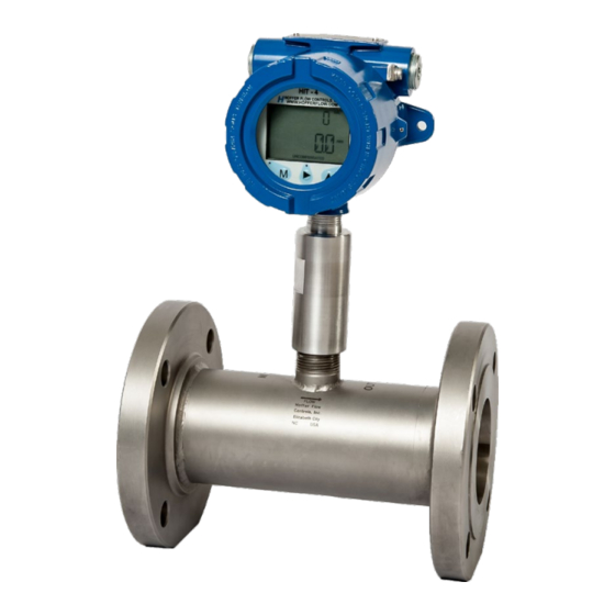
- Page 1 Model: HIT-4L Liquid Flow Rate Indicator & Dual Totalizer with Modbus & Data Logging USER’S MANUAL HP- 329 April 2021 107 Kitty Hawk Lane P.O. Box 2145 Elizabeth City, NC 27909 ● ● 1-800-628-4584 (252) 331-1997 Fax (252) 331-2886 ●...
- Page 3 NOTICE Hoffer Flow Controls, Inc. makes no warranty of any kind with regard to this material, including, but not limited to, the implied warranties of merchantability and fitness for a particular purpose. This manual has been provided as an aid in installing, connecting, calibrating, operating, and servicing this unit.
- Page 4 LIMITED WARRANTY POLICY FOR HOFFER FLOW CONTROLS HOFFER FLOW CONTROLS, INC. ("HFC") warrants HFC's Precision Series, API Series and CT Series of turbine flowmeters to be free from defects in material and workmanship under normal use and service, only if such goods have been properly selected for the service intended, properly installed and properly operated and maintained as described in the turbine flowmeter manual.
-
Page 5: Table Of Contents
Front Panel ------------------------------------------- 33 Saving Total ------------------------------------------ 33 Clearing the Total ---------------------------------- 34 Displaying Logs ------------------------------------- 34 Fault Conditions ------------------------------------ 35 Battery Replacement ------------------------------- 35 MODBUS COMMUNICATIONS ---------------------- 37 7. HIT-4 COMMUNICATION PROGRAM ------------ 46 MAINTENANCE ------------------------------------------ 63 HIT-4L HP-329... - Page 6 APPENDIX A - Declaration of Conformity ...... 65 APPENDIX B - Installation Drawings and Conditions for Safe Use for Certified System ... 67 HP-329 HIT-4L...
-
Page 7: Introduction
Introduction 1 1. INTRODUCTION The HIT-4L is a microprocessor-based liquid flow rate indicator and totalizer with data logger and Modbus Communications Protocol. The instrument can accept a low-level signal from a magnetic type pickup coil, a DC pulse signal, contact closure or modulated carrier pickup (MCP/RF). - Page 8 Residential, Commercial & Light Industry Environment. Generic Immunity Standard EN 61000-6-1 Residential, Commercial & Light Industry Environment. Electrostatic discharge requirements EN 61000-4-2 Radiated, radio-frequency, electromagnetic immunity EN 61000-4-3 Electrical fast transient/burst requirements EN 61000-4-4 Immunity to conducted disturbances EN 61000-4-6 HP-329 HIT-4L...
-
Page 9: Model Number Designation
(7)* STAINLESS STEEL ENCLOSURE (IP66) PANEL MOUNT ENCLOSURE (IP40) Note: Panel option not available for AC powered HIT-4G or HIT-4L (PD) PANEL MOUNT ENCLOSURE WITH CLEAR DOOR AND LOCK (IP40) Note: Panel option not available for AC powered HIT-4G or HIT-4L... - Page 10 MODEL HIT-4( )-( )-( )-( ) OPTION ( G ) NO COMPENSATION, ALWAYS USE X ON HIT-4U DEFAULT TEMPERATURE / PRESSURE COMPENSATION ON HIT-4L (TP1_) TEMPERATURE AND PRESSURE TRANSMITTER INPUTS (4-20MA) (TP2_) 100 OHM RTD (DIN385) / PRESSURE TRANSMITTER INPUTS (4-20MA)
- Page 11 USE WITH A (X-ATEX) RISER. INCLUDES “E2” JUNCTION BOX. UNION OPTIONS: (___U1) OPTIONAL 1" MALE X 1" FEMALE EX-PROOF UNION NOTE: USE WITH MX AND RX OPTIONS (___U2) OPTIONAL 3/4" MALE X 3/4" FEMALE EX-PROOF UNION NOTE: USE WITH MA AND RA OPTIONS HIT-4L HP-329...
- Page 12 SPECIAL FEATURES MODEL HIT-4( )-( )-( )-( ( J ) OPTION CE MARK REQUIRED FOR EUROPE (SP) ANY SPECIAL FEATURES THAT ARE NOT COVERED IN THE MODEL NUMBER USE A WRITTEN DESCRIPTION OF THE -SP. NO SPECIAL FEATURES HP-329 HIT-4L...
-
Page 13: Features And Specifications
Total and Grand Total saved when pressing ►button. Data Logging: Hourly Total, Daily Total, Event Logs • Modbus Communications Protocol via RS485 • Real Time Clock • Up to 20-Point table for liquid density and viscosity • HIT-4L HP-329... -
Page 14: General
0.001 to 9,999,999. Linearization: 2-20 points. Decimal Points: Decimal Point positions are configurable for 0, 0.0, 0.00, or 0.000 for rate, total and K-factor. Accuracy: Total and Rate: ±0.01% of reading, ±1 Count Density and Viscosity Compensation: 2-20 points HP-329 HIT-4L... -
Page 15: Flowmeter Inputs
*4-20 mA input not available with battery power. DC Power/Loop Powered Voltage: 8 to 30 VDC Current: < 24 mA Loop Burden: 8 VDC maximum Supply Backup: One C-size 3.6V lithium or battery pack for Ex system Protection: Reverse polarity protected HIT-4L HP-329... -
Page 16: Battery Powered Version
Event Log: Accessing Logs: Via Modbus communication. Up to 100 latest logs are viewable on the front panel 2.11 Physical Temperature: Operating: -40°F (-40°C) to 158°F (70°C). Humidity: 0 – 90% Non-condensing. Packaging: Explosion proof (Approx. 5"x5"x5", 3 lbs.) HP-329 HIT-4L... -
Page 17: Installation
Field wiring connections All field wiring connections should be made using shielded cables. The shield should be connected to the chassis ground lug on the HIT-4L enclosure. The shield on the opposite end of the cable should be left open. Connections are made to the HIT-4L terminal blocks using wire gauges 26-16 AWG, tightening Torque 0.22 to 0.25Nm. - Page 18 12 Installation Analog RS485 Flow+ Magnetic Tx A RS485 Pickup Flow- Tx B PCA192 Hoffer Flow Controls 1 2 3 4 5 6 Battery Powered with Magnetic Pickup Analog RS485 Flow+ Contact Tx A RS485 Flow- Tx B Closure PCA192...
- Page 19 Installation 13 Analog Load RS485 Flow+ Magnetic Tx A RS485 Pickup Flow- Tx B PCA192 Hoffer Flow Controls 1 2 3 4 5 6 Loop Powered with Magnetic Pickup Analog Load RS485 Flow+ Contact Tx A RS485 Closure Flow- Tx B...
- Page 20 Load RS485 RediPulse Flow+ Tx A RS485 Pickup Flow- Tx B TTL (0-5VDC) PCA192 Hoffer Flow Controls 1 2 3 4 5 6 DC Powered with Analog Output and RediPulse Pickup (0-5V/TTL) Pulse+ Pulse- Alarm+ Analog Alarm- Load RediPulse RS485...
- Page 21 Tx A RS485 Pickup Flow- Tx B Open Collector PCA192 Hoffer Flow Controls 1 2 3 4 5 6 * Jumper is required if 4-20mA is not connected DC Powered (no analog output) with RediPulse Pickup (Open Collector) Pulse+ Pulse- Alarm+...
- Page 22 Alarm- 4-20mA Load RS485 Flow+ Magnetic Tx A RS485 Pickup Flow- Tx B PCA192 Hoffer Flow Controls 1 2 3 4 5 6 DC Powered with Analog Output and Magnetic Pickup Pulse+ Pulse- Analog PCA193 Alarm+ Alarm- 4-20mA Load Flow+...
- Page 23 Tx A Flow- PCA193 Tx B PCA192 1 2 3 4 5 6 DC Powered with Temperature and Pressure Transmitters 100 Ohm Flow+ Tx A Flow- PCA193 Tx B PCA192 1 2 3 4 5 6 Two-Wire RTD Connection HIT-4L HP-329...
- Page 24 CONNECTOR RS485 PORT Flow- Tx B (NEMA 4 ENCL ONLY) TO USER PCA192 RS485 PORT Hoffer Flow Controls 1 2 3 4 5 6 ENSURE JUMPER J8 IS INSTALLED AS SHOWN RS485 Communications Port Wiring TO HIT-4 USB TO PERSONAL COMPUTER OR...
-
Page 25: Ma Current Loop
8-30 Volts DC is required, depending on the loop load resistance. At nominal 250 Ohms loop resistance the minimum power supply is 13V. Backup batteries are included to ensure that volume accumulation will not be interrupted during a power failure. HIT-4L HP-329... -
Page 26: Analog Output Update Time
Region Supply Voltage The HIT-4L outputs a 4-20mA analog signal that is proportional to the calculated flow rate. The 4mA and 20mA settings referred to as OUT LO and OUT HI respectively, may be configured from the front panel of the instrument or via Modbus communications. -
Page 27: Pulse Output
Installation 21 Pulse Output HIT-4L provides an optional Pulse Output factory configured for turbine raw frequency or scaled pulse. The scaled pulse outputs one pulse for the least significant digit of the displayed total. A scaling factor of 0.01, 0.1, 1, 10 or 100 is available to reduce or increase the resolution of the pulse output. -
Page 28: Alarm Output
22 Installation Alarm Output HIT-4L provides an optional Alarm Output configurable for Rate or Total. The Alarm Output can be configured as Low Alarm, High Alarm or Low/High. High Set Low Set Point Point LOW ALARM Not Active Active HIGH ALARM... -
Page 29: Temperature And Pressure Inputs
Installation 23 Temperature and Pressure Inputs HIT-4L provides inputs for temperature and pressure using an add-on printed circuit board PCA193. SW1 on PCA193 must be properly set according to the type of input being used. PCA193 INPUT OPTION SW-1 SETTINGS... - Page 30 24 Installation This page intentionally left blank HP-329 HIT-4L...
-
Page 31: Configuration
Configuration 25 4. CONFIGURATION The HIT-4L may be configured locally from the front panel, or remotely using Hoffer HIT-4 Communication program or a Modbus master. Front panel configuration may be done with magnetic pointer through the glass cover, or pressing front panel keys when cover is off. - Page 32 Clear Total Clear Total Accepts Sele ction Done Clear Total Next Menu Item Next Option Next Digit 10000000 Set Total Set Total Incr eaments Digit Accepts Sele ction Next Menu Item 10000000 Set Total Next Menu Software Item Version HP-329 HIT-4L...
- Page 33 20mA Password Units Function Pressure Lock Rate Total Default Unit Decimal Set Point Pressure Sample Low Cut off Rate Low Reference Time Frequency Set Point Pressure Contract Rate High Default Hour Set Point Density Reference Hourly Density Daily HIT-4L HP-329...
- Page 34 (0) to EEPROM. Grand Total is non-resettable. SETTOT Set Total and Numeric save to Entry 99999999 EEPROM. SW VER Read-only displays HIT-4L software version. DATE Current Date mm-dd-yy 01-01-10 (mm-dd-yy) TIME Current time in hh-mm-ss 23-00-00 24-hour format. ID NUM...
- Page 35 TOTL D Total Decimal Point 0.00 0.000 RATE /sec /sec /min Time base for flow rate. /hour /day RATE D Rate Decimal Point 0.00 0.000 CUTOFF Low flow frequency Numeric 0.000 0.000 cutoff threshold in Hz. Entry 100.000 HIT-4L HP-329...
- Page 36 K 01 K factor points Numeric 0.001 1.000 2 - 20 Entry 9999999.9 MODBUS MENU Menu Item Description Options Default Value ADDRSS Modbus address Numeric 000-254 entry BAUD Baud rate for 9600 9600 RS485 *57600 *115200 *Not currently supported. HP-329 HIT-4L...
- Page 37 RATE HI RATE LOHI TOTAL TEST Total alarm set Numeric TOTSET 0.001 1000.00 point. Entry 9999999 Rate alarm low set Numeric LO SET 10.00 point. Entry 999999 Rate alarm high set Numeric HI SET 100.00 point. Entry 999999 HIT-4L HP-329...
-
Page 38: Default Configuration
Entry 100 lb/gal Default Configuration HIT-4L is fully configured by the factory prior to shipment. When the instrument is purchased with a Hoffer Flowmeter or when calibration and configuration data are supplied, the instrument is configured as specified. When calibration or configuration data is not available, the instrument is shipped with default values. -
Page 39: Operation
Accepts numerical entry Moves to the next digit Increments digits The HIT-4L displays flow total and flow rate on a two-line liquid crystal display (LCD). The display is updated once per second. The 8-digit non-resettable Grand Total, Temperature and Pressure can be viewed on the top line by pressing the ▲... -
Page 40: Clearing The Total
To return to operating mode Displaying Logs HIT-4L records up to 768 hourly logs, 378 daily logs and 345 event logs. Data logs can be red via Modbus. The newest 99 Hourly and Daily logs can be displayed on the front panel by accessing the Log Menu. -
Page 41: Fault Conditions
To return to Press ▲ To return to operating mode Fault Conditions The HIT-4L detects numerous system faults and sends error message via Modbus. (Refer to chapter 6. Modbus Communications.) Battery Replacement The HIT-4L monitors the battery voltage and displays... - Page 42 Operation This page intentionally left blank HP-329 HIT-4L...
-
Page 43: Modbus Communications
Modbus Communications 6. MODBUS COMMUNICATIONS HIT Com Software or a Modbus Master may be used to configure HIT- 4L, monitor process variables and obtain diagnostic information from the HIT-4L. Supported Commands Function Code Description (Hex) Read holding registers Preset Boolean (for Enron event record... - Page 44 Hour 1-24 1204 Minute 0-59 1205 Second 0-59 2000 Total Units 0=gal, 1=bbl, 2=L, 3=lb, 4=kg, 5=acf, 6=acfx1000, 7=scf, 8=scfx1000, 9=m3, 10=nm3 2001 Total Decimal Point 2003 Rate Time Base 0=sec, 1=min, 2=hr, 3=day 2004 Rate Decimal Point HP-329 HIT-4L...
- Page 45 K-Factor 9 FP32 0.001-9999999 2053 K-Factor 10 FP32 0.001-9999999 2055 K-Factor 11 FP32 0.001-9999999 2057 K-Factor 12 FP32 0.001-9999999 2059 Frequency 13 FP32 0.001-5000.000 2061 Frequency 14 FP32 0.001-5000.000 2063 Frequency 15 FP32 0.001-5000.000 2065 Frequency 16 FP32 0.001-5000.000 HIT-4L HP-329...
- Page 46 Rate Alarm High FP32 0.001- Max limited by Set Point rate decimal point selection: 999.999, 9999.99, 99999.9, 99999 7000 Request Hourly FP32 -1 (cleared logs) - 767 Log Pointer 7001 Request Daily FP32 -1 (cleared logs) - 383 Log Pointer HP-329 HIT-4L...
- Page 47 0 – Max limited by total Total decimal point selection: 99999.999, 999999.99, 9999999.9, 99999999. This register is also used to clear total by writing 0 or set total by writing desired value. 16-bit registers available at address 7052-7055 (FP64) and 7060-7061 (FP32) HIT-4L HP-329...
- Page 48 7056-7059 Request Grand FP64 Grand Total stored in Total four 16-bit registers 7060-7061 Request Current FP32 Current Total stored in Total two 16-bit registers Total is reset by sending a read request to register HP-329 HIT-4L...
- Page 49 Calibrate RTD Write 5000 to calibrate High Read for A/D counts 8020 Request Flow FP32 Flowing Temperature Temperature 8021 Request Flow FP32 Flowing Pressure Pressure 8022 Request Flow FP32 Flowing Density Density 8023 Request Flow FP32 Flowing Z Compressibility HIT-4L HP-329...
- Page 50 32-bit in two consecutive 16-bit registers. The 64-bit format is recommended for greater precision, especially with values greater than 7-digits. Temperature, Pressure, Density and Viscosity are available in † 16-bit registers in firmware versions 1.020821 and later. HP-329 HIT-4L...
- Page 51 Flash segment 1 invalid Flash segment 2 invalid Maximum input frequency exceeded EEPROM read error on startup Code execution error Flow rate exceeds 20mA setting Temperature Input Fail Pressure Input Fail Flash Segments Table Invalid Spare 2 Spare 1 HIT-4L HP-329...
-
Page 52: Hit-4 Communication Program
HIT-4 Communication Program This page intentionally left blank HP-329 HIT-4L... - Page 53 To start communication with the HIT-4: Open the program by clicking on the HIT-4 icon on the desktop, or navigate the program file located at C:\Program Files (x86)\Hoffer Flow Controls\HIT-4 and double click on the file “Hit4Master.exe”. The “Com Port” screen will appear.
- Page 54 “Disconnect” and click “Connect”. 6. When communication is established with HIT-4 the Connecting to device widow will appear: Click “Yes” to read HIT-4 configuration information. Once the configuration has been successfully read, the following window will pop-up: HP-329 HIT-4L...
- Page 55 “Found Devices” field as well in the “Slave Address” drop down box. • Select the desired device address from the “Slave Address” drop down box. • Click on the “Connect” button to establish communication with the field device. HIT-4L HP-329...
- Page 56 1 to 80, where 80 represents 8.0 seconds. Contract Hour: Determines the time when the daily log begins. Valid entries are 1 to 24. Set Total: Set Total to user defined value. Valid entries 0 to 99999999. HP-329 HIT-4L...
- Page 57 The frequency cutoff threshold in Hz. The HIT-4 will ignore an input frequency that is below this user entered value. Valid entries are 0.000 to 100.000. K-Factor Decimal: Sets location of the K-Factor decimal point. Select 0, 1, 2 or 3. HIT-4L HP-329...
- Page 58 The K-Factor Units parameter is provided for convenience and is not stored in the device. Outputs Page The Outputs Configuration screen is used to configure the Analog, Alarm and Pulse outputs. HP-329 HIT-4L...
- Page 59 Sets total alarm set point. Valid entries 0 to 99999999. Max value is determined by Total Decimal selection. Pulse Output: Drop down menu selection; Off: turns off pulse out turns on pulse out Test: outputs a test frequency of 1Hz, 50% duty cycle HIT-4L HP-329...
- Page 60 Drop down menu selection: RTD: 100 Ohm, DIN385 4-20mA: 4 to 20mA temperature transmitter Temperature Units: Drop down menu selection: C: Degrees Celsius F: Degrees Fahrenheit Temperature Min: Temperature value for 4mA input. Valid entries -450F to 999F (-267.8C to 537.2C). HP-329 HIT-4L...
- Page 61 (0 bar to 3447.4 bar). Pressure Calibrate 4mA: Connect 4mA source to pressure input and press 4mA button to calibrate Min. Pressure Calibrate 20mA: Connect 20mA source to pressure input and press 20mA button to calibrate Max. HIT-4L HP-329...
- Page 62 The Fluid Properties Table page is used to define fluid density and viscosity over the temperature and pressure ranges. The buttons at the bottom of the page are used load table from liquid properties file, save to file, upload from the device and download to the device. HP-329 HIT-4L...
- Page 63 The configuration may be printed by clicking on the “Print” button located on the bottom of any of the configuration screens. When the “Print” button is clicked on, the user has the option to select a printer for printing or saving the configuration as a text file. HIT-4L HP-329...
- Page 64 Clicking on the “Update” button will read and display the “Flow Total”, “Grand Total”, “Flow Rate”, “Current Day Total”, “Previous Day Total”, "Temperature", "Pressure", "Density", and "Viscosity". Refresh Rate (sec): Sets update rate in seconds when the Flow Readings are taken in the automatic update mode. HP-329 HIT-4L...
- Page 65 Faults currently active are displayed in the “Active” window. Faults that have occurred in the past, since the last power reset, are displayed in the “Since Power On” window. The numerical code displayed above each window is used for factory diagnostics. HIT-4L HP-329...
- Page 66 Logs”, “Daily Logs” and “Event Log”. Logs are downloaded by clicking on the drop down “Select Log” box, and selecting the desired log to be downloaded. Once the selection has been made, either click on the “Download New” or “Download All” menu options. HP-329 HIT-4L...
- Page 67 Multiple records can be selected by clicking on the first and last desired records to be marked as read. Selected record(s) will be highlighted in blue. Clicking on the “Mark as Read” menu selection will mark all highlighted records as read and change the new data logs status. HIT-4L HP-329...
- Page 68 HIT-4 Communication Program This page intentionally left blank HP-329 HIT-4L...
-
Page 69: Maintenance
. Replace the batteries only with battery pack part number 100-2732 for Ex d certified systems. WARNING: The lithium battery that powers the HIT-4L is a sealed unit; however, should Lithium batteries develop a leak, toxic fumes could escape upon opening the enclosure. Ensure that the instrument is in a well-ventilated area before opening the enclosure to avoid breathing fumes trapped inside the enclosure. - Page 70 After replacing the battery, set the date and time via the HIT-4 Communication Program or use the front panel keys. Battery shelf life is estimated at 10 years at a storage temperature of 25° C. HP-329 HIT-4L...
- Page 71 Appendix A – Declaration of Conformity APPENDIX A DECLARATION OF CONFORMITY HIT-4L HP-329...
- Page 72 Appendix A – Declaration of Conformity HP-329 HIT-4L...
- Page 73 Appendix B – Installation Drawings and Conditions for Safe Use for Certified Systems APPENDIX B INSTALLATION DRAWINGS AND CONDITIONS FOR SAFE USE FOR CERTIFIED SYSTEMS HIT-4L HP-329...
- Page 74 Appendix B – Installation Drawings and Conditions for Safe Use for Certified Systems HP-329 HIT-4L...
- Page 75 Appendix B – Installation Drawings and Conditions for Safe Use for Certified Systems HIT-4L HP-329...
- Page 76 Appendix B – Installation Drawings and Conditions for Safe Use for Certified Systems HP-329 HIT-4L...
- Page 77 Appendix B – Installation Drawings and Conditions for Safe Use for Certified Systems HIT-4L HP-329...
- Page 78 Appendix B – Installation Drawings and Conditions for Safe Use for Certified Systems HP-329 HIT-4L...
- Page 79 Appendix B – Installation Drawings and Conditions for Safe Use for Certified Systems HIT-4L HP-329...
- Page 80 Appendix B – Installation Drawings and Conditions for Safe Use for Certified Systems HP-329 HIT-4L...
- Page 81 Appendix B – Installation Drawings and Conditions for Safe Use for Certified Systems HIT-4L HP-329...
- Page 82 Appendix B – Installation Drawings and Conditions for Safe Use for Certified Systems HP-329 HIT-4L...
- Page 83 Appendix B – Installation Drawings and Conditions for Safe Use for Certified Systems HIT-4L HP-329...
- Page 84 Appendix B – Installation Drawings and Conditions for Safe Use for Certified Systems HP-329 HIT-4L...
- Page 85 Appendix B – Installation Drawings and Conditions for Safe Use for Certified Systems HIT-4L HP-329...
Need help?
Do you have a question about the HIT-4L and is the answer not in the manual?
Questions and answers