
Related Manuals for GESTRA NRS 1-54


Summarization of Contents
Important Notes
Usage and Function
Explains the application, principle, and control modes of the level switch.
Safety Precautions
Details safety requirements for installation, operation, and handling potential electrical hazards.
Directives and Standards
VdTÜV Bulletin "Wasserstand 100"
States type approval and requirements for water level control equipment.
Low Voltage and EMC Directives
Confirms compliance with LV Directive 2014/35/EU and EMC Directive 2014/30/EU.
ATEX Compliance
Notes that the equipment must not be used in explosion risk areas without specific measures.
Declaration of Conformity
Refers to online availability of conformity declarations for European Directives.
Technical Data
NRS 1-54, NRS 1-55 Specifications
Details supply voltage, fuse, power consumption, electrode connection, response sensitivity, outputs, indicators, housing, and electrical safety.
Operating and Storage Conditions
Lists ambient, transport, storage temperatures, and relative humidity limits.
Approvals and Scope of Supply
Mentions TÜV certificate, type approval, and contents of the delivery for NRS 1-54 and NRS 1-55.
In control cabinet: Mounting level switch
Dimensions and Mounting
Shows dimensions of the unit and how it clips onto a supporting rail (TH 35).
Key and Installation
Explains the terminal strips, housing, supporting rail, and clipping mechanism.
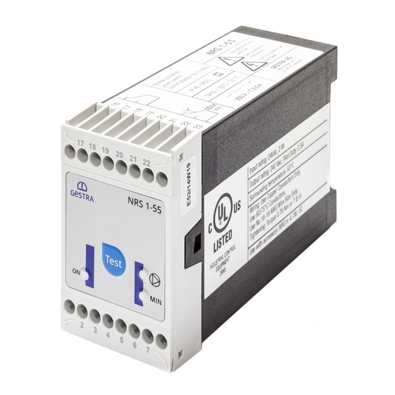
Name plate / marking
Details information found on the top and bottom name plates, including type designation, safety notes, and electrical ratings.
In control cabinet: Wiring level switch
Wiring Diagram NRS 1-54 / NRS 1-55
Provides detailed wiring diagrams for MAX (NRS 1-54) and MIN (NRS 1-55) configurations.
Key for Wiring Diagram
Explains the numbering and symbols used in the wiring diagrams.
Connecting Supply Voltage
Specifies requirements for the 24 V DC supply, including fuse and isolation standards.
Connecting Output Contacts
Instructions for wiring output contacts and handling inductive loads.
Connection of Level Electrode
Details cable requirements, wiring, and screen connection for level electrodes.
Tools Required
Lists the necessary tools, specifically insulated screwdrivers.
In the plant: Wiring level electrode
NRS 1-54: Connecting multiple electrodes (fill control)
Shows wiring examples for NRS 1-54 with different electrode types (NRG 10-52, NRG 16-36, NRG 16-4, ER 5...).
Key for Electrode Wiring
Identifies the level electrode types and the central earthing point.
NRS 1-55: Connecting multiple electrodes (drain control)
Shows wiring examples for NRS 1-55 with different electrode types (NRG 10-52, NRG 16-36, NRG 16-4, ER 5...).
Key for Electrode Wiring
Identifies the level electrode types and the central earthing point.
Level electrode connection overview
Lists compatible level electrodes and cable connection guidelines.
Factory settings
Details default response sensitivity and function for NRS 1-54 and NRS 1-55.
Commissioning Procedure
Danger Warning
Reiterates the danger of electric shock and the need to cut off power.
Changing response sensitivity and function
Outlines the steps to change settings using the code switch.
Changing response sensitivity
Explains how to adjust sensitivity based on water conductivity.
Changing function settings
Provides a table for setting the fill or discharge control function via code switch S1-S3.
NRS 1-54: Checking switchpoint and function
Details the steps and expected results for verifying the switchpoints and function of NRS 1-54.
NRS 1-54: MAX alarm and fault checking
Covers MAX alarm conditions, potential installation faults, and remedies for NRS 1-54.
NRS 1-55: Checking switchpoint and function
Details the steps and expected results for verifying the switchpoints and function of NRS 1-55.
NRS 1-55: MIN alarm and fault checking
Covers MIN alarm conditions, potential installation faults, and remedies for NRS 1-55.
Operation, Alarm and Test
NRS 1-54: Indicators and Adjustors
Explains the indicators (LEDs, buttons) and their functions during fill, discharge, and test modes.
NRS 1-55: Indicators and Adjustors
Explains the indicators (LEDs, buttons) and their functions during fill, discharge, and test modes for NRS 1-55.
Further Notes
Action against high frequency interference
Provides measures to suppress high-frequency interference.
Decommissioning / replacing the equipment
Outlines the procedure for safely removing and replacing the unit.
Disposal
Advises on proper disposal according to legal regulations.
Need help?
Do you have a question about the NRS 1-54 and is the answer not in the manual?
Questions and answers