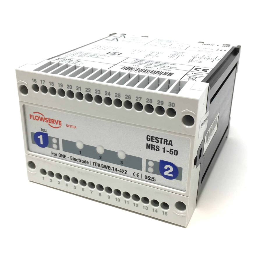
GESTRA NRS 1-50 Original Installation & Operating Manual
Level switch
Hide thumbs
Also See for NRS 1-50:
- Original installation & operating manual (36 pages) ,
- Original installation instructions (28 pages) ,
- Instruction manual (2 pages)

Subscribe to Our Youtube Channel
Related Manuals for GESTRA NRS 1-50


Summary of Contents for GESTRA NRS 1-50
- Page 1 Level Switch NRS 1-50 For ONE electrode Original Installation & EN (USA) Operating Manual 850693-00 English...
-
Page 2: Table Of Contents
Connecting the signal output ......................20 Wiring diagram of level switch NRS 1-50 ..................21 Connection example for Class C ..................... 22 Example switching combinations ....................23 NRS 1-50 For ONE electrode - USA - Installation & Operating Manual - 850693-00... - Page 3 Action against high-frequency interference ..................29 Interlock and interlock deactivation ....................29 Checking switchpoints ........................29 Taking out of service .......................... 30 Disposal .............................. 30 UL components ........................... 30 NRS 1-50 For ONE electrode - USA - Installation & Operating Manual - 850693-00...
-
Page 4: Content Of This Manual
The General Terms & Conditions of GESTRA AG apply. Scope of supply, product package NRS 1-50 1 level switch NRS 1-50 1 Installation & Operating Manual NRS 1-50 For ONE electrode - USA - Installation & Operating Manual - 850693-00... -
Page 5: How To Use This Manual
How to use this Manual This Installation & Operating Manual describes the correct use of the NRS 1-50 level switch. It applies to persons who integrate this equipment in control systems, install, bring into service, operate, maintain and dispose of this equipment. Anyone carrying out the above-mentioned activities must have read this Installation &... -
Page 6: Types Of Warning
Warning of a situation that may result in minor or moderate injury. ATTENTION Warning of a situation that results in damage to property or the environment. NRS 1-50 For ONE electrode - USA - Installation & Operating Manual - 850693-00... -
Page 7: Specialist Terms, Abbreviations
A boiler that is operated at 145 psi (10 bar) and 356°F (180°C) may be designed to withstand a pressure of 870 psi (60 bar) and a temperature of 527°F (275°C), for example, which is therefore not necessarily its operating point. NRS 1-50 For ONE electrode - USA - Installation & Operating Manual - 850693-00... -
Page 8: Usage For The Intended Purpose
Usage for the intended purpose The NRS 1-50 level switch is used in conjunction with the NRG 1...-50 level electrode as a water level limiter for steam boilers and hot water installations. Water level limiters switch off the heating when the water drops below the set low water level (LW). -
Page 9: Basic Safety Information
Check that the plant is not carrying live voltage before commencing work. ■ Attempts to repair the equipment will cause the plant to become unsafe. The NRS 1-50 level switch may only be repaired by the manufacturer, GESTRA AG. ■ Only replace faulty equipment with identical equipment from GESTRA AG. -
Page 10: Required Personnel Qualifications
Refits Specialist staff with pressure and temperature. Notes on product liability The manufacturer cannot accept any liability for damages resulting from improper use of the equipment. NRS 1-50 For ONE electrode - USA - Installation & Operating Manual - 850693-00... -
Page 11: Function
In addition, the signal contact for external signaling devices closes without a delay. The NRS 1-50 level switch must be used in combination with an external manual reset when used as a protective device per ASME CSD-1. -
Page 12: Technical Data
Site altitude Max. 6560 ft (2000 m) Other information ■ Incorporated Type 2 action protective control Class B (C) ■ Pollution degree 2, impulse voltage 2500 V NRS 1-50 For ONE electrode - USA - Installation & Operating Manual - 850693-00... -
Page 13: Rating Plate, Identification
Input rating: 100-240VAC, 7W Fig. 2 Frequency: 50/60Hz Output rating : Pilot duty B300 / R300 NRS 1-50 For ONE electrode - USA - Installation & Operating Manual - 850693-00 Ambient temperature: 32 131°F (0 55°C) Wiring: Use Copper Conductors Only, OPERATING CONTROL Use 60/75°C Conductors,... -
Page 14: Factory Default Settings
Switch off the voltage to the plant before you install the equipment. ■ Check that the plant is not carrying live voltage before commencing work. ■ NRS 1-50 For ONE electrode - USA - Installation & Operating Manual - 850693-00... -
Page 15: Dimensions Of The Nrs 1-50
9 10 11 12 13 14 15 Fig. 3 Upper terminal strip Lower terminal strip Fastening screws (cross recess head screw M3) Terminal box Support rail TH 35, EN 60715 NRS 1-50 For ONE electrode - USA - Installation & Operating Manual - 850693-00... -
Page 16: Important Notes
Attention Pay attention to regulations in your country, e.g., NEC, NFPA, CEC, when using this equipment. NRS 1-50 For ONE electrode - USA - Installation & Operating Manual - 850693-00... -
Page 17: Preparing For Installation
Take further measures to protect the equipment from lightning, insects and ■ animals, and salty air. You will need the following tools: Pozidriv screwdriver size PZ1 ■ NRS 1-50 For ONE electrode - USA - Installation & Operating Manual - 850693-00... -
Page 18: Installation
ATTENTION Incorrect installation can lead to malfunctions in the plant or the level electrode. The NRS 1-50 level switch snaps onto a TH 35, EN 60715 support rail in a control cabi- net. Fig. 3 5 NRS 1-50 For ONE electrode - USA - Installation & Operating Manual - 850693-00... -
Page 19: Electrical Connection
24 and 26. Provide the output contacts with a slow blow T1A fuse. Note In the event of an alarm, the NRS 1-50 level switch interlock does not take place ■ automatically. -
Page 20: Connecting The Signal Output
A safety power supply unit (SELV / PELV / CLASS2) must be used to supply the ■ NRS 1-50 level switch with 24 V DC. This must provide a level of isolation against dangerous contact voltages that at least meets the requirements for double or reinforced insulation in accordance with UL 60730-1 (protective electrical isolation). -
Page 21: Wiring Diagram Of Level Switch Nrs 1-50
Signal output 1 / 2 for external alarm 24 V DC, 100 mA (semiconductor output) Safety circuit, input and output Wire jumper, provided by customer Level electrode NRG 1...-50 CGP Central grounding point in control cabinet NRS 1-50 For ONE electrode - USA - Installation & Operating Manual - 850693-00... -
Page 22: Connection Example For Class C
Reset IN Reset button Signal 1 17 18 19 20 21 22 23 24 NRS 1-50/51 Test Signal 2 Reset OUT 11 12 Fig. 5 NRS 1-50 For ONE electrode - USA - Installation & Operating Manual - 850693-00... -
Page 23: Example Switching Combinations
Fig. 6 Fig. 7 Fig. 8 Fig. 9 Safety circuit Level electrode NRG 1...-50 Level switch NRS 1-50 for advance low water alarm Level switch NRS 1-50 NRS 1-50 For ONE electrode - USA - Installation & Operating Manual - 850693-00... - Page 24 Figure 8 Combination consisting of 1x NRG 1...-50 level electrode plus 1x NRS 1-50 level switch as a water level limiter and 1x NRG 1...-50 level electrode plus 1x NRS 1-50 level switch as an advance low water alarm. Figure 9 Combination consisting of 2x NRG 1...-50 level electrodes plus 2x NRS 1-50 level switches as...
-
Page 25: Bringing Into Service
Check level electrode installation and make sure Upper pressure relief that the level in the protective tube corresponds hole is flooded. to the actual water level. NRS 1-50 For ONE electrode - USA - Installation & Operating Manual - 850693-00... -
Page 26: Operation, Alarm And Test
LED lights were an alarm. Signal output closed. Test is complete. If the test is failed, replace the level switch. NRS 1-50 For ONE electrode - USA - Installation & Operating Manual - 850693-00... -
Page 27: Fault Indications And Troubleshooting
Once the error has been rectified, the level switch reverts to normal operation. After troubleshooting, please switch the supply voltage off and on again after approx. 5 s. NRS 1-50 For ONE electrode - USA - Installation & Operating Manual - 850693-00... -
Page 28: Checking The Level Electrode
Fig. 11 CGP Central grounding point in control cabinet Note The self-test of the NRS 1-50 level switch cyclically reduces U , possibly to ■ 0 V. NRS 1-50 For ONE electrode - USA - Installation & Operating Manual - 850693-00... -
Page 29: Important Notes
■ Suppress HF interference using hinged-shell ferrite rings. Interlock and interlock deactivation In the event of an alarm, the NRS 1-50 level switch interlock does not take place automatically. If the installation requires an interlock, this must be implemented in the external (safety) circuit. -
Page 30: Taking Out Of Service
■ rail Disposal Dispose of the level switch in accordance with statutory waste disposal regulations. UL components The NRS 1-50 level switch is registered under XACN.E513189. NRS 1-50 For ONE electrode - USA - Installation & Operating Manual - 850693-00... - Page 31 For your notes NRS 1-50 For ONE electrode - USA - Installation & Operating Manual - 850693-00...
- Page 32 You can find our authorized agents around the world at: www.gestra.com GESTRA AG Münchener Straße 77 28215 Bremen Germany Tel. +49 421 3503 0 +49 421 3503 393 e-mail info@de.gestra.com www.gestra.com 850693-00/09-2021cm (809136-00) · GESTRA AG · Bremen...
Need help?
Do you have a question about the NRS 1-50 and is the answer not in the manual?
Questions and answers