Table of Contents
Advertisement
Quick Links
Manual
Cube 300S Telemetry System
Part No. 0062090 | 0062100 | 0062210 | 0062220 | 0062110 | 0062230 | 0034390 | 0034400 | 0034410
Information subject to change without notice. In-Situ, In-Situ logo, Baro Merge, BaroTROLL, HERMIT, HydroVu™, iSitu, Pocket-Situ, RDO, RuggedCable,
©
RuggedReader, SmarTROLL™, TROLL, VuSitu, and Win-Situ are trademarks or registered trademarks of In-Situ Inc.
2016. All rights reserved. This product
0061030 | 2019-03-14
may be covered by patents identified at www.in-situ.com/patents
Advertisement
Table of Contents

Subscribe to Our Youtube Channel
Related Manuals for In-situ Cube 300S


Summary of Contents for In-situ Cube 300S
- Page 1 Cube 300S Telemetry System Part No. 0062090 | 0062100 | 0062210 | 0062220 | 0062110 | 0062230 | 0034390 | 0034400 | 0034410 Information subject to change without notice. In-Situ, In-Situ logo, Baro Merge, BaroTROLL, HERMIT, HydroVu™, iSitu, Pocket-Situ, RDO, RuggedCable, ©...
- Page 2 800-446-7488 (U.S.A. & Canada) In-Situ makes no warranty of any kind with regard to this material, including, but not limited to, its fitness for a particular application. In-Situ will not be liable for errors contained herein or for incidental or consequential damages in connection with the furnishing, performance, or use of this material.
-
Page 3: Table Of Contents
Model Number Serial Number Safety General Specifications 3 Configuring Your Instruments Overview Connecting an In-Situ Instrument to the Computer Changing Instrument Communication Settings Changing Instrument Communication Settings - TROLL 9500 Only Setting Up a Log 4 Configuring the Telemetry Device Overview... - Page 4 SIM Card SD Card Warranty Obtaining Repair Service 8 Appendix - Alarms Alarms - Overview Absolute Mode Incremental Mode Probe Out of Range SMS Alarms in Absolute Mode Probe Out of Range SMS Alarms in Incremental Mode 800-446-7488 www.in-situ.com...
-
Page 5: Introduction
Your Cube Telemetry System was carefully inspected before shipping. Inspect the package for any physical damage sustained during shipment. Notify In-Situ and file a claim with the carriers involved if there is any damage. Do not attempt to operate the instrument when damage has occurred. -
Page 6: Serial Number
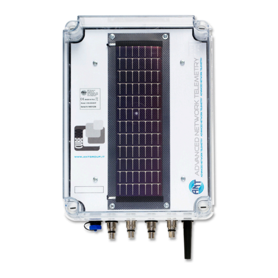
Rugged TROLL connection, while a "T" means titanium Twist-lock connection. Therefore, the example model number means the following: C3S-3G-B-5T: Cube 300S (solar), 3G, non-vented, 5 Twist-lock connections Serial Number The unit serial number is printed on the product label affixed to the unit body. This number is important for warranty and service purposes. -
Page 7: General Specifications
1 year from date of shipment Configuring Your Instruments Overview Cube 300S systems support up to 5 In-Situ devices. You must change communication settings on your devices so they can transmit data to the Cube. Connecting an In-Situ Instrument to the Computer Laptop or PC ®... -
Page 8: Changing Instrument Communication Settings
In-Situ instrument * TROLL Com device may be a USB-connect, serial-connect, or direct-connect** model ** RuggedCable is omitted when using a direct-connect TROLL Com Changing Instrument Communication Settings Complete the following steps for each instrument you want to connect to the Cube. -
Page 9: Setting Up A Log
Configuring the Telemetry Device Overview If you purchased a data plan through In-Situ, you need to open the unit and connect the battery, and then set up the Cube using the configuration software. If you are using a 3rd party data plan, you will need to install the SIM card prior to setting up the Cube with the configuration software. -
Page 10: Connecting The Cube To The Computer
Connecting the Cube to the Computer 1. Connect the setup cable to the communication port of the Cube and to the computer. 2. Download the ANT Tube Tool software from www.in-situ.com/support 3. Install and open the ANT Tube Tool software. -
Page 11: Set Level Reference
1. Click General information, parameters and functional options. 2. Click the Information tab. 3. Enter a site name for your deployment area and click Set the Site Name. 4. Click Set clock to synchronize the Cube clock with your computer clock. 5. Close the window. 800-446-7488 www.in-situ.com... -
Page 12: Configure Options
1. Click General information, parameters and functional options. 2. Click the Communication (1) tab. 3. Enter the Access point name (APN) in the field under "Access Point". If you purchased a SIM card and data plan through In-Situ, your access point name is: For KORE SIM cards:... -
Page 13: Activate Alarms
Set Wake Up Events The Cube can be programmed with up to 8 different wake up periods. A wake up period is when the Cube sends data, sends a status text message, or waits for an external connection. 800-446-7488 www.in-situ.com... -
Page 14: Restart Device And Test Communications
10. Close the window. Digital, Pulse, and Analog Input The Cube supports digital, pulse, or analog device input via a stripped-and-tinned cable that connects to the Cube communication port. This device can be set up in the Tube Tool. 800-446-7488 www.in-situ.com... -
Page 15: Wiring Diagram
Connecting the Cube to the Computer 1. Connect the setup cable to the communication port of the Cube and to the computer. 2. Download the ANT Tube Tool software from www.in-situ.com/support 3. Install and open the ANT Tube Tool software. -
Page 16: Field Installation
The Cube includes four plastic mounting adapters that can be attached to the pre-drilled holes on the back of the enclosure using the provided screws. In-Situ recommends using bolts to secure the plastic mounting brackets to your deployment location. If you are deploying the Cube using the Wall Mounting Adapter (PN 0062330), use appropriate hardware to attach the Cube to the adapter using the pre-drilled holes. -
Page 17: Troubleshooting
5. Verify signal quality. See "Activate the Modem" on page 18. 6. Verify the current band and network. In-Situ recommends 850/900 MHz dual-band and Automatic, 3G preferred for the Western Hemisphere, and 850/900/1800/1900 quad-band and Automatic, 3G preferred for the Eastern Hemisphere. See "Activate the Modem"... -
Page 18: Error Codes And Messages
Recipient email address rejected by server. Error 882-884 Email error. Activate the Modem Activate the modem if the Test FTP functionality returns an error. 1. Click Functional mode and test. 2. Click the Modem, settings, and tests tab. 800-446-7488 www.in-situ.com... -
Page 19: Sim Card
The Cube has a 512 MB SD Mini memory card installed. The system will not function without an SD card. Warranty In-Situ warrants the Cube Telemetry System for one year from date of shipment by the end user against defects in materials and workmanship under normal operating conditions. To exercise this warranty contact Technical Support for a Return Material Authorization (RMA) and further instructions. -
Page 20: Obtaining Repair Service
ATTN: Repairs 221 East Lincoln Avenue Fort Collins, CO 80524 The warranty does not cover damage during transit. In-Situ recommends insurance for all shipments. Warranty repairs will be shipped back prepaid. Outside the U.S. Contact your international In-Situ distributor for repair and service information. -
Page 21: Absolute Mode
In Absolute Mode, alarms and warnings occur when a measurement value is less than the minimum threshold value or greater than the maximum threshold value. Minimum Level Value Maximum Level Value Measurement Value Result ALARM ALARM ALARM ALARM ALARM 800-446-7488 www.in-situ.com... -
Page 22: Incremental Mode
The Cube can send SMS (text) messages when alarms are triggered. SMS alarms are enabled in the General Information, Parameters, and Functional Options section on the Alarms tab. Below is an example situation showing when SMS messages would be sent for the "Reading from Probe Out of Range" alarm with the following settings. 800-446-7488 www.in-situ.com... -
Page 23: Probe Out Of Range Sms Alarms In Incremental Mode
The Cube can send SMS (text) messages when alarms are triggered. SMS alarms are enabled in the General Information, Parameters, and Functional Options section on the Alarms tab. Below is an example situation showing when SMS messages would be sent for the "Reading from Probe Out of Range" alarm with the following settings. 800-446-7488 www.in-situ.com... - Page 24 Incident C: No SMS alarm is sent. Only one consecutive set of measurements exceed the alarm threshold, while the requirement set above is 3 consecutive measurements. In this scenario, SMS alarms are disabled for the rest of the day after the third SMS message is sent. 800-446-7488 www.in-situ.com...
Need help?
Do you have a question about the Cube 300S and is the answer not in the manual?
Questions and answers