Table of Contents
Advertisement
Quick Links
Operator's Manual
®
RDO
PRO-X Process Optical Dissolved Oxygen Probe
Information subject to change without notice. In-Situ, In-Situ logo, Baro Merge, BaroTROLL, HERMIT, HydroVu™, iSitu, Pocket-Situ, RDO,
©
RuggedCable, RuggedReader, SmarTROLL™, TROLL, VuSitu, and Win-Situ are trademarks or registered trademarks of In-Situ Inc.
2008-
0090102 | 2019-05-10
2015. All rights reserved. This product may be covered by patents identified at www.in-situ.com/patents
Advertisement
Table of Contents

Related Manuals for In-situ RDO PRO-X


Summary of Contents for In-situ RDO PRO-X
- Page 1 ® PRO-X Process Optical Dissolved Oxygen Probe Information subject to change without notice. In-Situ, In-Situ logo, Baro Merge, BaroTROLL, HERMIT, HydroVu™, iSitu, Pocket-Situ, RDO, © RuggedCable, RuggedReader, SmarTROLL™, TROLL, VuSitu, and Win-Situ are trademarks or registered trademarks of In-Situ Inc.
- Page 2 Apple Inc., registered in the U.S. and other countries. The Bluetooth word mark and logos are registered trademarks owned by the Bluetooth SIG, Inc. and any use of such marks by In-Situ Inc. is under license. NIST is a registered trademark of the National Institute of Standards and Technology, U.S.A.
-
Page 3: Table Of Contents
Table of Contents 1 Optical RDO PRO-X Dissolved Oxygen Probe Specifications 2 Introduction System Description Serial Numbers Unpack the Probe 3 Calibrate the RDO PRO-X Probe 1-Point Calibration Water-Saturated Air 2-Point Calibration 100% and 0% Saturation 4 Probe Deployment 5 Care and Maintenance... - Page 4 100% Saturation Calibration Values 0% Saturation Calibration Values Calibration Slope and Offset Entering Calibration Registers Calibration Calculations 10 Service Sensor Health Table 11 Appendix A - Communication Device Install and Open the Software Connect the Probe to the Communication Device 12 Declaration of Similarity...
-
Page 5: Optical Rdo Pro-X Dissolved Oxygen Probe Specifications
Optical RDO PRO-X Dissolved Oxygen Probe Specifications Optical RDO PRO-X Dissolved Oxygen Probe Sensor Type Optical (luminescent) dissolved oxygen sensor Range: 0 to 60 mg/L concentration Accuracy: ±0.1 mg/L from 0 to 20 mg/L RDO PRO-X Probe ±2% of reading from 20-60 mg/L Resolution: 0.01 mg/L... -
Page 6: Introduction
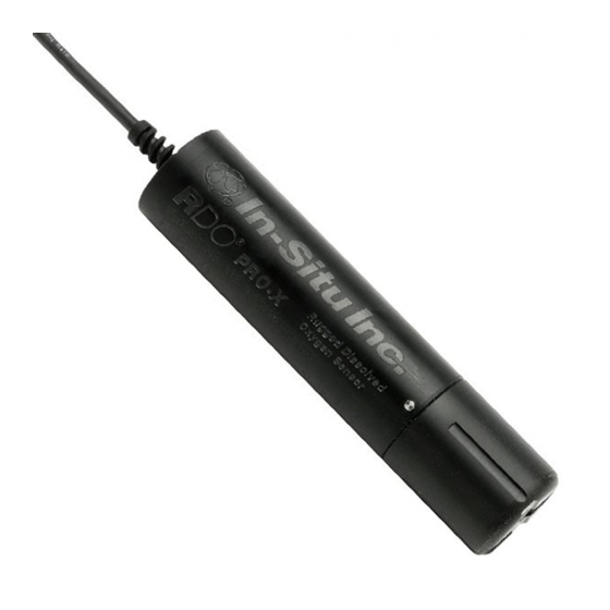
Introduction The RDO PRO-X Probe is a rugged, reliable instrument designed to deliver accurate dissolved oxygen (DO) data across a wide measurement range and to reduce maintenance costs. The probe features the latest optical technology for DO measurement. System Description The RDO PRO-X system consists of the following items. -
Page 7: Serial Numbers
Probe Cable end, twist-lock connector and RuggedCable System Serial Numbers The probe serial number is engraved on the side of the unit. The cap serial number is programmed on the memory chip inside the cap. Unpack the Probe 1. Remove the probe from the box and other packaging materials. 2. - Page 8 Alignment arrow on cap Cap installed over lens Nose cone Do not allow moisture or atmospheric humidity inside the cap. Keep the cap in its sealed package until you are ready to install it. Install promptly. Ensure that O-ring grooves are dry and that the O-ring is not rolled or pinched inside the cap.
-
Page 9: Calibrate The Rdo Pro-X Probe
Calibrate the RDO PRO-X Probe Calibrate the sensor with Win-Situ 5 software or the VuSitu mobile app, or calibrate directly with your controller. 1-Point Calibration The optical Rugged Dissolved Oxygen sensor is very stable. The factory calibration should produce readings within 3% accuracy. - Page 10 1. Set up the calibration procedure as previously described, and perform a water-saturated air calibration. 2. Remove the water-saturated sponge from the calibration chamber and fill the chamber to the fill line with approximately 60 mL of fresh sodium sulfite solution. Fill line Temperature sensor 2.
-
Page 11: Probe Deployment
Probe Deployment The cable end of the RDO PRO-X Probe is internally threaded (1¼ – 11½ NPT) and can be attached to a male threaded pipe. When deployed, make sure that the nose cone and thermistor are completely submerged. 10 m cable attached... -
Page 12: Care And Maintenance
Care and Maintenance Clean the Sensor Cap 1. The cap and nose cone must remain on the probe. 2. Rinse the sensor with clean water from a squirt bottle or spray bottle. 3. Gently wipe with a soft-bristled brush or soft cloth if biofouling is present. Use Alconox to remove grease. 4. -
Page 13: Maintain Desiccant
8. Remove the new cap from its sealed packaging and attach it to the sensor, being careful to press firmly, without twisting, until it seals over the lens. Make sure that the O-rings are not pinched or rolled between the cap and sensor. -
Page 14: Controller Requirements And Connections
Controller Requirements and Connections The RDO PRO-X Probe may be connected to a controller or logger for communication via the following options. Analog (4-20 mA) provides a configurable 4-20 mA current loop output SDI-12 RS485 Modbus RS232 to Modbus Wiring Overview Refer to diagrams on the following pages. -
Page 15: Analog (4-20 Ma) 3-Wire
Analog (4-20 mA) 3-wire Signal Color Ground/Return Black External Power (12-36 VDC) 4-20 mA Brown Cable length must not exceed 1219 m (4000 ft.) Analog signal must be enabled in Win-Situ 5 Software or the Comm Kit Software prior to use. -
Page 16: Sdi-12 (3-Wire)
SDI-12 (3-wire) Signal Color Ground/Return Black External Power (9.6-16 VDC) RS485 (-) Green RS485 (+) Blue SDI-12 White Cable length must not exceed 60.96 m (200 ft.) -
Page 17: Modbus Master With Built-In Rs485
Modbus Master with Built-in RS485 Signal Color Ground/Return Black External Power (12-36 VDC) RS485 (-) Green RS485 (+) Blue Cable length must not exceed 1219 m (4000 ft.) -
Page 18: Modbus Master With Built-In Rs232 (Converter Required)
Modbus Master with Built-in RS232 (Converter Required) Signal Color Ground/Return Black External Power (12 VDC, voltage limited by converter) RS485 (-) Green RS485 (+) Blue Cable between converter and master must not exceed 60.96 m (20 ft.) Cable between master and slave must not exceed 1219 m (4000 ft.) -
Page 19: Converter
Converter Power Connections The red wire provides power for all system modes. Analog output is disabled by default. However, the 4-20 mA current loop output can be continuous in Modbus or SDI-12 mode as long as Modbus device register 9507 is set to 1. Communications The device automatically switches between Modbus and SDI-12 modes depending on which of the two interfaces has activity. -
Page 20: Modbus Registers
Modbus Registers Common Registers Mode & Register Size Access Level Data Type Description (R/W) Device ID = 19 for RDO Titan31 for RDO PRO-X35 for 9001 ushort RDO Blue 9002 ulong Device serial number 9004 time Manufacture date Sensor Status Registers Mode &... -
Page 21: Device Specific Registers
Device Specific Registers Mode & Register Size Access Level Data Type Description (R/W) Dissolved Oxygen Concentration Measured value, C 0038 float 0040 ushort Parameter ID = 20 Units ID 0041 R1/W2 ushort 117 = mg/L (default) 118 = ug/L 0042 ushort Data quality ID (See the Sensor Health Table) 0043... -
Page 22: Dissolved Oxygen Equations
Dissolved Oxygen Equations Dissolved Oxygen Concentration DO concentration is internally calculated in mg/L. Conversion to other units is as follows:... -
Page 23: Dissolved Oxygen, % Saturation
Dissolved Oxygen, % Saturation... -
Page 24: Calibration Registers
Calibration Registers Mode & Access Register Size Data Type Description Level (R/W) 0118 R1/W3 float Live salinity value (PSU) 0120 R1/W3 float Default salinity value (PSU, default = 0.0) 0122 R1/W3 float Live barometric pressure (mbar) 0124 R1/W3 float Default barometric pressure (mbar, default = 1013.25) 0126 R1/W3 float... -
Page 25: Calibration Slope And Offset
Calibration Slope and Offset These values represent the slope and offset that will be applied to the raw concentration reading from the sensor to generate the final values reported by the sensor parameters. These registers may be written independently of the normal internal calibration procedure. -
Page 26: Calibration Calculations
Calibration Calculations... -
Page 27: Service
Service The RDO PRO-X contains no user-serviceable parts. Do not attempt to open the probe case or service the unit yourself. RDO Software Troubleshooting Sensor health diagnostics indicate when the RDO sensor has been damaged in the field. If the sensor has sustained moderate damage, the probe provides a DO value that includes a (DIS or Data Quality ID 5) warning. -
Page 28: Appendix A - Communication Device
Appendix A - Communication Device The Communication Device is an accessory product that can be used to calibrate and set up RDO probes. Install and Open the Software The Comm Kit Software must be installed on a computer before you connect to the probe. Connect the Probe to the Communication Device The Communication Device connects a stripped-and-tinned probe to a computer via USB connection. -
Page 29: Declaration Of Similarity
Declaration of Similarity...
Need help?
Do you have a question about the RDO PRO-X and is the answer not in the manual?
Questions and answers