Advertisement
Quick Links
Compliance Products USA, Inc
CAL-Fac-001-MP-CDT 240 Rev 2.3
ORIGINATOR:
QUALITY ASSURANCE:
DOCUMENT EFFECTIVE DATE:
1.0
TITLE
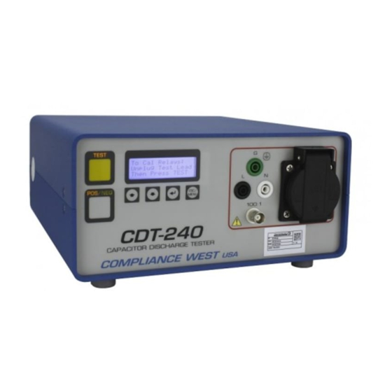
Calibration procedure for CDT-240.
2.0
PURPOSE
To describe the CDT-240 calibration procedure.
3.0
DEFINITIONS
DMM - Digital Multimeter
CAL-BOX - Calibration Box (00-CDT-CBX)
4.0
PRECAUTIONS
4.1
The CDT-240 tester is capable of generating high voltage. Be very careful to follow all
directions in the procedure.
5.0
MATERIALS/EQUIPMENT NEEDED
5.1
Calibrated DMM (Qty 2) DMM1 for voltage RMS below 50V and the DMM2 for
voltages RMS 50V or greater.
5.2
Calibrated Oscilloscope ( with 10x or 100x probe )
5.3
DC power supply 60V
5.4
BNC cable, 1:1 ratio
5.5
Screwdrivers
6.0
PROCEDURE
6.1
Once a technician has been trained on this procedure by an appropriate person, follow the
directions listed in Appendix 1.
6.2
An appropriate person shall be any technician that has performed the calibration of a
CDT-240 tester and can explain the procedure and safety concerns.
7.0
APPENDICES
7.1
Appendix 1
8.0
RELATED ITEMS
8.1
CAL-Log-001-CDT 240
8.2
CBX1V Video
SIGN OFF
CDT-240 Factory Calibration Procedure.
Page 1 of 13
DATE
Advertisement

Related Manuals for Compliance West CDT-240


Summary of Contents for Compliance West CDT-240
- Page 1 DMM - Digital Multimeter CAL-BOX - Calibration Box (00-CDT-CBX) PRECAUTIONS The CDT-240 tester is capable of generating high voltage. Be very careful to follow all directions in the procedure. MATERIALS/EQUIPMENT NEEDED Calibrated DMM (Qty 2) DMM1 for voltage RMS below 50V and the DMM2 for voltages RMS 50V or greater.
-
Page 2: Software Version Verification
001-CDT 240, use the specifications given here in the current document instead of mentioned CAL- Log. 2.2. Plug in the CDT-240 power cord, plug in the EUT power cord to the proper value (90 – 260V 50/60Hz), disconnect all the test leads attached to G, L or N outputs, disconnect any power cord attached to the front panel socket. - Page 3 Compliance Products USA, Inc CAL-Fac-001-MP-CDT 240 Rev 2.3 Page 3 of 13 3. Zero Volt Adjustment (P3). 3.1. Connect the Oscilloscope to the BNC 100:1 output of the CDT-240. 3.2. Set the CDT for the following test: • Trigger on POS •...
- Page 4 4.1. Connect the L and G front panel test jacks across the RC time constant CAL-BOX, 0.1s terminals “C” and “D” as shown in Figure 4. Figure 4. CDT-240 with CAL-BOX attached. 4.2. Set the CDT for the following test (same as previous test): •...
- Page 5 Page 5 of 13 5. Internal Voltage Measurement Accuracy (P5 & P2). 5.1. Line to Ground (P5) 5.1.1. Connect the Oscilloscope to the BNC 100:1 output of the CDT-240. 5.1.2. Edit the test parameters for a Voltage test: • Trigger on NEG •...
- Page 6 Compliance Products USA, Inc CAL-Fac-001-MP-CDT 240 Rev 2.3 Page 6 of 13 Figure 6. Internal Voltage Measurement Test Points TP6, TP7 y TP8. 5.1.6. Record the result on section 4 (L-G) of CAL-Log-001-CDT 240. 5.1.6.1. EUT Test Voltage: DMM2 Line to Ground voltage readout. 5.1.6.2.
- Page 7 Compliance Products USA, Inc CAL-Fac-001-MP-CDT 240 Rev 2.3 Page 7 of 13 6. BNC 100:1 Calibration (P1) 6.1. Line to Ground Calibration. 6.1.1. Disconnect the scope and connect DMM1 Volts AC to the BNC 100:1 connector and DMM2 Volts AC to “L” and “G”. 6.1.2.
- Page 8 Compliance Products USA, Inc CAL-Fac-001-MP-CDT 240 Rev 2.3 Page 8 of 13 6.2.2. Edit the test parameters for a Voltage test: • Trigger on NEG • Voltage Test • Voltage setting: 50.0V • Neutral to Ground measurement 6.2.3. Press TEST once to ARM the CDT. 6.2.4.
- Page 9 Compliance Products USA, Inc CAL-Fac-001-MP-CDT 240 Rev 2.3 Page 9 of 13 7. Main Relay (off-board): Disconnect at Peak 7.1. All measurements within +5% of maximum (peak) voltage +5% = + 18.2° from peak (cos (.95)) equates to + 0.84 ms for 60 Hz, + 1.01 ms for 50 Hz 7.2.
- Page 10 Compliance Products USA, Inc CAL-Fac-001-MP-CDT 240 Rev 2.3 Page 10 of 13 7.4. Accuracy at 120V, 60 Hz input, POS peak. 7.4.1. Connect an oscilloscope to the 100:1 BNC connector on the front panel of the CDT. 7.4.2. Connect the L and G front panel test jacks across the RC time constant CAL-BOX, 1s terminals “A’...
- Page 11 8.2.5.2. Tolerance voltage: Waveform value voltage ±2% of reading ±0.8V. 8.2.5.3. As left voltage: This is the value of the voltage result on the CDT-240 (50V +0V -0.8V). 8.2.6. Return back the polarity of the EUT to normal connection.
- Page 12 9.1.4.1. Expected value: Voltage level at 1s. Note: Compensate for oscilloscope offset. 9.1.4.2. Tolerance voltage: Waveform value voltage ±2% of reading ±0.8V. 9.1.4.3. As left voltage: This is the value of the voltage result on the CDT-240. 9.2. Line to Neutral: Voltage Accuracy.
- Page 13 9.3.7.2. Expected value: Voltage level at 1 second. Note: Compensate for oscilloscope offset. 9.3.7.3. Tolerance voltage: Waveform value voltage ±2% of reading ±0.8V. 9.3.7.4. As left voltage: This is the value of the voltage result on the CDT-240. 9.3.8. Return the polarity of the EUT to normal connection.
Need help?
Do you have a question about the CDT-240 and is the answer not in the manual?
Questions and answers