Advertisement
Installing an Expansion Module in the SSR 2000
: Before performing any upgrade or installation procedures, ensure that the
Warning
SSR 2000 is powered off and that you are properly grounded to avoid electrostatic
discharge while working inside the SSR 2000's chassis.
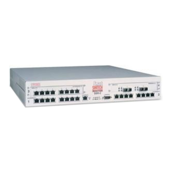
It may be necessary at some point for you to upgrade or replace your SSR 2000's
expansion module(s) after receiving your SSR 2000 from Cabletron. You can install any of
the available expansion modules in either of the SSR 2000's expansion slots.
Note:
You can also reference material on installing an expansion module in the
SmartSwitch Router 2000 Getting Started Guide.
To install an expansion module:
1.
Ensure that the SSR 2000 is powered off.
2.
If your SSR 2000 is equipped for rackmountability, use the phillips-head screwdriver
to remove the mounting brackets from each side of the SSR 2000.
3.
Take off the SSR 2000's top cover.
a.
Use the phillips-head screwdriver to remove the four mounting screws (two on
each side of the router, front and back) that hold the top cover on the SSR 2000.
b. Slide the cover away from the front of the SSR 2000 about 1/2", then lift it away
from the SSR 2000.
4.
Use the phillips-head screwdriver to remove the four mounting screws in the existing
face plate or cover plate corresponding to the expansion slot where you plan to install
the expansion module. Be sure not to damage or remove the conductive tape on the
inside of the chassis, both above and below the expansion slot opening. (See
below.)
SSR-2
3
10/100BASE-TX
1
2
3
4
5
6
7
8
10/100 MGMT
1
ERR
Figure 1. Removing the SSR 2000's cover
2000
1
2
3
4
5
6
7
8
10/100BASE-TX
CONSOLE
OK
HBT
DIAG
39-078-01
4
2
Figure
2,
1
Advertisement
Table of Contents

Related Manuals for Cabletron Systems SSR 2000


Summary of Contents for Cabletron Systems SSR 2000
- Page 1 DIAG Figure 1. Removing the SSR 2000’s cover b. Slide the cover away from the front of the SSR 2000 about 1/2”, then lift it away from the SSR 2000. Use the phillips-head screwdriver to remove the four mounting screws in the existing face plate or cover plate corresponding to the expansion slot where you plan to install the expansion module.
- Page 2 This step applies only if you are installing a 100 Base-FX module (part number SSR-2- FX). In order for the 100 Base-FX module to be aligned properly in the SSR 2000’s chassis, 5-millimeter extensions must be attached to the six standoffs holding the module in place on the SSR 2000’s motherboard.
- Page 3 10/100BASE-TX CONSOLE DIAG Figure 4. Attaching 5-mm extensions to the standoffs on the SSR 2000 motherboard (necessary only when installing an SSR-2-FX module) Insert the expansion module from the top and ensure that it makes maximum surface contact with its face plate.
- Page 4 Figure 5. Installing an expansion module 10. Replace the SSR 2000’s cover. When you are ready to attach the segment cables, use the procedures in “Attaching Port Cables” in the SmartSwitch Router 2000 Getting Started Guide. Installing an Expansion Module on the SSR 2000...
Need help?
Do you have a question about the SSR 2000 and is the answer not in the manual?
Questions and answers