Ruijie Reyee RG-RAP6260 Hardware Installation And Reference Manual
Hide thumbs
Also See for Reyee RG-RAP6260:
- Configuration manual (126 pages) ,
- Configuration manual (219 pages)
Table of Contents
Advertisement
Quick Links
Advertisement
Table of Contents

Related Manuals for Ruijie Reyee RG-RAP6260


Summary of Contents for Ruijie Reyee RG-RAP6260
- Page 1 Ruijie Reyee RG-RAP6260(G) Access Point Hardware Installation and Reference Guide...
- Page 2 Ruijie Networks reserves all copyrights of this document. Any reproduction, excerption, backup, modification, transmission, translation or commercial use of this document or any portion of this document, in any form or by any means, without the prior written consent of Ruijie Networks is prohibited. Exemption statement This document is provided “as is”.
- Page 3 It is intended for the users who have some experience in installing and maintaining network hardware. At the same time, it is assumed that the users are already familiar with the related terms and concepts. Obtaining Technical Assistance Ruijie Networks Website: https://www.ruijienetworks.com/ Technical Support Website: https://ruijienetworks.com/support...
-
Page 4: Product Overview
· 1 Product Overview RG-RAP6260(G) supports 802.11ax and provides dual-radio and dual-band performance speeding up to 575Mbps@2.4G + 1200Mbps@5G. The IP68 design adapts to inclement outdoor environments such as the cold and humidity. This substantially simplifies installation and maintenance. RAP6260(G) supports PoE to take over challenges in a wide variety of deployment scenarios, including large-scaled campuses, enterprises, hospitals and Wi-Fi hotspots. -
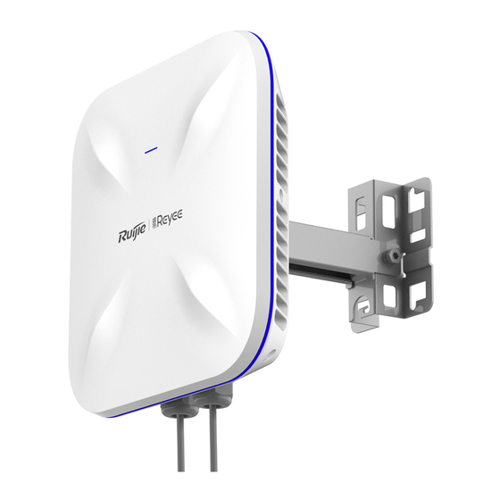
Page 5: Product Image
· One LED (blue) Power Supply PoE: IEEE 802.3at (PoE+) Warning:802.3af or non-standard POE adapter may cause unknown issues. Please use Ruijie POE+ switch Power Consumption Maximum: 17W Operating: -40℃ to 65℃ (-40℉ to 149℉) Temperature Storage: -40℃ to 85℃ (-40℉ to 185℉) -
Page 6: Led Indicators
State Frequency Meaning The AP is NOT receiving power. Slow Blinking 0.5Hz Normal operation, but the device is not connected to Ruijie Cloud. Fast Blinking 10Hz 1. Restoring the factory settings. 2. Upgrading the firmware. 3. Restoring the image file. - Page 7 The RG-RAP6260(G) supports Cloud management. To reset the device, you can bring the device online and reset it on Ruijie Cloud. If the device can not access the Internet, power on the device, press the reset button with a thin rod (as shown in the figure) for more than 5 seconds, and the device will restore the factory settings.
-
Page 8: Preparing For Installation
· 2 Preparing for Installation To prevent device damage and bodily injury, please read carefully the safety recommendations described in this chapter. The recommendations do not cover all possible hazardous situations. 2.1 Installation The AP must be installed indoors. To ensure its normal operation, the installation site must meet the foll owing requirements. -
Page 9: Temperature And Humidity
2.7 Power Supply PoE injector: IEEE 802.3at compliant The input power should be greater than the power actually consumed by the system. The input power for the RG-RAP6260(G) should be greater than 18W. Please use Ruijie certified PoE injectors. -
Page 10: Installation Tools
· 2.8 Installation Tools Common Tools Phillips screwdriver, related copper and fiber cables, bolts, diagonal pliers, cable ties Special Tools Wire stripper, crimping pliers, RJ-45 crimping pliers, punch down tool Meter Multimeter, bit error rate tester (BERT) The listed tools are customer supplied. 2.9 Unpacking the Access Point Package Contents Verify that all parts are installed and debugged. -
Page 11: Installation Flowchart
· 3 nstalling the Access Point Before installing the AP, make sure you have carefully read the requirements described in Chapter 2. 3.1 Installation Flowchart 3.2 Before You Begin Before you install the AP, verify that: The installation site provides sufficient ventilation for the AP. ... -
Page 12: Installing The Access Point
· 3.3 Precautions The device can be mounted on a wall or a pole (diameter: 50 mm to 70 mm). If the diameter of the pole is out of the range, the hose clamp is customer-supplied (thickness ≥ 2.5mm). The installation site can vary due to on-the-spot surveys conducted by technical personnel. - Page 13 · Use M8x60 expansion bolts to implement the wall mount. Attach the bracket to the wall and mark the screw hole locations. Secure the mounting bracket on the wall using M8x60 expansion bolts. Figure 3-2 Installing the Bracket Align the host with bracket and mounting plate to the bracket on the wall, and tighten the M8x20 screws to complete installation.
- Page 14 · Align the host with bracket and mounting plate to the bracket on the pole, and tighten the M8x20 screws to complete installation. Figure 3-5 Vertical Pole Mounting Pole mount (Horizontal) Attach the bracket to a pole with hose clamps and fasten the clamps with screws and nuts. Figure 3-6 Mounting the Bracket on a Pole Align the host with bracket and mounting plate to the bracket on the pole, and tighten the M8×20 screws to complete installation.
-
Page 15: Connecting Cables
· Angle Adjustment To cover the specified area, adjust the angle (five stages from 0 to 60 Figure 3-8 Adjust the Angle When the angle of the access point is properly adjusted, secure the access point with M4x10 screws in the position shown in Note 1. -
Page 16: Bundling Cables
· 2. Run a network cable or fiber (optional) through the joint according to the order shown in the figure, and combine parts B and C and place them in part A. 3. Screw part D, and wear the joint tightly with a waterproof tape. Figure 3-9 Cable Connection The waterproof materials are customer supplied. - Page 17 · Checking Cable Connection Make sure the UTP/STP cable matches the interface type. Make sure cables are properly bundled. Checking the Power Supply Make sure all power cables are properly connected and safe. Make sure the AP is operational after power-on.
-
Page 18: System Debugging
· 4 System Debugging 4.1 Setting up a Debugging Environment Power on the AP through PoE. Setting up the Environment Verify that the AP is properly connected to the power source. When the AP is connected to a PC for debugging, verify that the PC and PoE switch are properly grounded. 4.2 Powering up the AP Checking before power-up ... -
Page 19: Monitoring And Maintenance
· 5 Monitoring and Maintenance 5.1 Monitoring You can observe the LED to monitor the AP in operation. 5.2 Hardware Maintenance If the hardware is faulty, please contact our Technical Assistance Center (TAC) for help. -
Page 20: Troubleshooting Flowchart
· 6 Troubleshooting 6.1 Troubleshooting Flowchart 6.2 Troubleshooting LED does not light up after the AP is powered on Verify that the power source is IEEE 802.11at compliant, and then verify that the cable is connected properly. Ethernet port is not working after the Ethernet port is connected Verify that the device at the other end of the Ethernet cable is working properly. - Page 21 · Verify that the AP is configured correctly. Move the client device to adjust the distance between the client and the AP.
-
Page 22: Appendix A Connectors And Media
· Appendix A Connectors and Media 1000BASE-T/100BASE-TX/10BASE-T The 1000BASE-T/100BASE-TX/10BASE-T is a 10/100/1000 Mbps auto-negotiation port that supports auto MDI/MDIX. Compliant with IEEE 802.3ab, 1000BASE-T requires Category 5e 100-ohm UTP or STP (STP is recommended) with a maximum distance of 100 meters (328 feet). 1000BASE-T requires all four pairs of wires be connected for data transmission, as shown in Figure A-1. -
Page 23: Appendix B Mini-Gbic Module Specifications
· Appendix B Mini-GBIC Module Specifications Ruijie provides various Gigabit SFP transceivers (Mini-GBIC modules) for interfaces of wireless access controllers. You can select the most suitable SFP modules as needed. This appendix describes the models and specifications of some of the Gigabit SFP transceivers for your reference. -
Page 24: Appendix C: Cabling Recommendations
· Appendix C: Cabling Recommendations During installation, route cable bundles upward or downward along the sides of the rack depending on the actual situation in the equipment room. All cable connectors should be placed at the bottom of the cabinet rather than be exposed outside of the cabinet. - Page 25 · If cables are to be bent, bind them first but do not tie cable ties within the bend to avoid stress on the cables, which may otherwise cause the wires inside to break, as shown in Figure B-3. Figure B-3 Do Not Tie Cable Ties within the Bend ...
- Page 26 · 3. Spring washer 1. Flat washer Note 4. Flat washer 2. Nut When using a stiff cable, fix it near the cable lug to avoid stress on the lug and cable. Do not use self-tapping screws to fasten terminals. ...
Need help?
Do you have a question about the Reyee RG-RAP6260 and is the answer not in the manual?
Questions and answers