Table of Contents
Advertisement
Quick Links
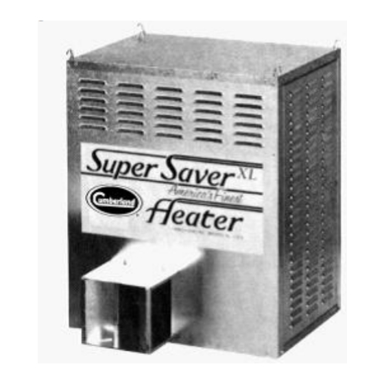
SUPER-SAVER XL
MODEL
SS-225-XL
SS-200-XL
SS-175-XL
SS-120-XL
SS-75-XL
SS-40-XL
FOR YOUR SAFETY
If you smell gas:
1. Open windows
2. Don't touch electrical switches
3. Extinguish any open flames
4. Immediately call your gas supplier
CONSIGNES DE SECURITE
Si vous sentez une odeur de gaz:
1. Ouvrez les fenetres
2. Ne touchez pas aux interrupteurs electriques
3. Etegnex toute flamme hue
4. Contactez immediatement votre compangie
de gaz
Cumberland 1004 E. Illinois St. Assumption, IL 62510 Phone 1-217-226-4421 Fax 1-217-226-4420
Owner's Manual
Agricultural Building Heater
BTUH
kW
225,000
65.9
200,000
58.6
175,000
36.6
120,000
35.2
75,000
21.9
40,000
11.7
Retain Instructions For Future Reference
Manual Part No. 4801-5300
TM
Hot Surface Ignition
FOR YOUR SAFETY
Do not store or use gasoline or any
flammable vapors and liquids in the
vicinity of this or any other appliance
CONSIGNES DE SECURITE
II es interdit dutiliser des liquides
inflammables ou degageant des
vapeurs inflammables, a proximite
de tout appareil fonctionnant au gaz
HEATER
Wash Down Design
Advertisement
Table of Contents

Related Manuals for Cumberland Super-Saver XL SS-200-XL


Summary of Contents for Cumberland Super-Saver XL SS-200-XL
- Page 1 4. Contactez immediatement votre compangie de tout appareil fonctionnant au gaz de gaz Retain Instructions For Future Reference Cumberland 1004 E. Illinois St. Assumption, IL 62510 Phone 1-217-226-4421 Fax 1-217-226-4420 Manual Part No. 4801-5300...
- Page 2 GENERAL HAZARD WARNING Failure to comply with precautions and instructions provided with this heater can result in death, serious bodily injury and property loss or damage from hazards of fire, explosion, burn, asphyxiation, carbon monoxide poisoning, and/or electrical shock. If you need assistance or heater information such as an instruction manual, labels, etc.
-
Page 3: Table Of Contents
Component And Wiring Diagram ....7 all of the listed parts are enclosed. Ladder Type Schematic Diagram ....9 not, call your Cumberland Servicing Instructions ........11 Distributor immediately. Pipe Sizing Guidelines ......... 16 Parts & Assemblies ........18 HEATER DIMENSIONS WEIGHT 130 lb. -
Page 4: Specifications And Requirements
Warnings and Cautions WARNING When Heater Is Connected To Remote Thermostat Heater May Start At Any Time! ELECTRICAL GROUNDING INSTRUCTIONS This appliance is equipped with a three prong (grounding) plug for your protection against electrical shock and should be plugged directly into a properly grounded three-prong receptacle. -
Page 5: Maintenance And Warranty
This appliance rating is based on the use of ANSI LC-2 test gases including LP (2500 BTU/ft 93.15 MJ/m ) and natural gas (1075 BTU/ft , 40 MJ/m ). Cumberland, Inc. makes no guarantees regarding the proper operation of this appliance when these conditions are not met. Part No. 4801-5300 Rev. 1-15 Page... - Page 6 5 to 7 years – end-user pays 50% Flooring All Fiberglass Housings Lifetime 7 to 10 years – end user pays 75% All Fiberglass Propellers Lifetime AP/Cumberland Flex-Flo/Pan Feeding Systems 2 Years ** Warranty prorated from list price: Feeder System Pan Assemblies 5 Years ** Cumberland 0 to 3 years –...
-
Page 7: Installation
Installation 5.1 Hanging The Heater Chain Suspension Cable Suspension Mount heater with screw hooks and chains so that back of heater is at least 12 inches (305 mm) from If frequent height adjustment is required, use ceiling and wall. Heater must be a minimum of 20 cables and pulleys. -
Page 8: User Instructions
User Instructions Before turning on gas, check main supply valve to be sure it is open (Fig. 3). Be sure to check all connections for leaks with a Gas Leak Testing solution, (soap and water work well). Check to see if gas valve knob is in the ON position. -
Page 9: Outside Mount (Optional)
Outside Mount (Optional) Cumberland heaters are available in Outside Mount (OSM) models. These heaters are designed to be mounted to the outside wall of a building. This saves valuable space inside the building and ensures fresh air intake for the heater. -
Page 10: Component And Wiring Diagram
Component and Wiring Diagram COMPONENT AND WIRING DIAGRAM THERMOSTAT TRANSFORMER DIAGNOSTIC INDICATOR ELECTRONIC MODULE 3 10 12 15 UNUSED CPC PINS Represents pin number on connector shell. FLAME PROBE BLACK CPC RECEPTACLE 10 AMP FUSE 13 14 SUPPLY * LOW GAS PRESSURE SWITCH ON/OFF CORD... - Page 11 COMPONENT AND WIRING DIAGRAM 240 Volts A.C. 50/60 Hz Single Phase Part No. 4801-5300 Rev. 1-15 Page Super Saver XL Heater...
-
Page 12: Ladder Type Schematic Diagram
Ladder Type Schematic Diagram LADDER TYPE SCHEMATIC DIAGRAM NEUTRAL LINE VOLTAGE GROUND THERMOSTAT LINE VOLTAGE ON / OFF LOW LINE 10 AMP FUSE 24 VAC-40VA, 50/60 Hz TRANSFORMER UNITED TECHNOLOGIES Hot Surface Ignition Control SILICONE CARBIDE IGNITER HSIG SAIL SWITCH FLAME SENSOR PROBE... - Page 13 LADDER TYPE SCHEMATIC DIAGRAM LEG 1 LINE VOLTAGE LEG 2 GROUND THERMOSTAT LINE VOLTAGE ON / OFF LOW LINE 10 AMP FUSE TRANSFORMER 24 VAC-40VA, 50/60 Hz UNITED TECHNOLOGIES Hot Surface Ignition Control TRANSFORMER 24 VAC-40VA, 50/60 Hz IGNITOR HSIG SAIL SWITCH FLAME SENSOR PROBE...
-
Page 14: Servicing Instructions
Servicing Instructions 10.1 United Technologies Hot Surface Ignition System IMPORTANT! Inspect and check operation of this appliance monthly. Follow the instructions below. If a problem is detected, contact a qualified technician to make any necessary repairs. In an effort to minimize the time required to trouble shoot this system: Turn off the gas supply at the main gas valve. - Page 15 power supply lines are improperly connected to the furnace. Reverse incoming line voltage leads. 10.2 1018 Series Hot Surface Ignition Status Indicator Error Conditions The status indicator LED will not be lit with power applied to the board and the control operating properly.
- Page 16 10.4 Chart 1 First Visual Check Part No. 4801-5300 Rev. 1-15 Page Super Saver XL Heater...
- Page 17 10.5 Chart 2 Second Visual Check Part No. 4801-5300 Rev. 1-15 Page Super Saver XL Heater...
- Page 18 10.6 Chart 3 Third Visual Check Part No. 4801-5300 Rev. 1-15 Page Super Saver XL Heater...
-
Page 19: Pipe Sizing Guidelines
Pipe Sizing Guidelines Determine the Equivalent Length Of Pipe (ELOP) 11.1 Calculating HVR & ELOP required for sufficient gas service. Using a system schematic, label each piping ELOP = (length from meter to most remote heater) section of the system starting at the meter or + (Minor loss equivalents of the system) regulator. - Page 20 Table 1 Minor Loss Equivalents 2” (5.08 cm) IPS To 4” (10.16 cm) IPS Fitting 2" (5.08 cm) IPS Or Smaller Feet per fitting Meters per fitting Feet per fitting Meters per fitting 45 Elbow 90 Elbow Gate Valve Angle Valve Swing Valve Pipe Sizes Determined For Diagram Pipe Section...
-
Page 21: Parts & Assemblies
Parts & Assemblies When ordering service parts, please specify the country, model number, date of manufacture, voltage, frequency, gas type, inside or outside mount, and whether the heater is constructed of galvanized or stainless steel. 6401-2889 (6401-2890) 3005-0107 (3005-0108) 1007-1614 6401-2879 3005-2130 (6401-2881) - Page 22 0404-2340 (0404-2738) 6401-1145 6401-2867 (6401-2866) 6401-1140 0404-2341 (0404-2739) 1004-1406 0404-2342 (0404-2740) 0408-4347 1004-7019 1001-1453 6401-1308 (6401-1307) 3002-5000 120V 3002-5000 120V 3002-3050 240V 3002-3050 240V (LP) 3002-5001 240V (NG) 3001-0111 1004-1102 1005-0100 1901-0162 1041-5004 (1901-0163) (1041-2427) 1009-1500 SEE MODEL NO. 1041-1488 1004-1422 1021-1495 1021-1500...
- Page 23 1004-1388 (0408-1883) 6401-2879 (6401-2881) 1004-0107 (1004-2881) 6401-1318 0408-1131 (6401-1726) (0408-1231) (0408-2314) SS-40-XL Only 1004-1412 0408-1146 1004-1388 3001-1740 3017-1301 120V 60Hz 3017-5029 200/230V 60Hz 0408-5017 (3017-1302) 120V 60Hz 3017-3076 240V 50 Hz 1001-1452 3591-0100 3591-1851 3008-2258 3008-2257 0404-2348 1902-1138 1902-1137 3006-1581 3006-1580 3001-2862 3001-2862...
- Page 24 Copyright © 2015 by The GSI Group, LLC Printed in the USA Part No. 4801-5300 Rev. 1-15 Page Super Saver XL Heater...
Need help?
Do you have a question about the Super-Saver XL SS-200-XL and is the answer not in the manual?
Questions and answers