
Related Manuals for Cumberland Super-Saver XL HH-SS-250-XL


Summary of Contents for Cumberland Super-Saver XL HH-SS-250-XL
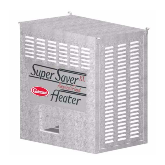
- Page 1 Super-Saver XL Heater Agricultural Building Heater 120V, 60 Hz, ETL Owner’s Manual 4801-1020 Version: 4.0 Date: 05-08-19 4801-1020...
- Page 2 Model BTUH HH-SS-250-XL 250,000 73.3 • Standing Pilot Ignition • Wash-Down Design • 120 Volt (only) All information, illustrations, photos and specifications in this manual are based on the latest information available at the time of publication. The right is reserved to make changes at any time without notice.
-
Page 3: Table Of Contents
Table of Contents Contents Chapter 1 Safety ..............................4 Safety Guidelines ...........................4 Cautionary Symbols Definitions ......................5 Safety Cautions ............................6 Safety Sign-Off Sheet ..........................11 Chapter 2 General Information ...........................12 Heater Dimensions ..........................13 Tools Required .............................13 Minimum Clearances ...........................13 Specifications and Requirements ......................13 Chapter 3 Installation ............................14 Hanging the Heater ..........................14... -
Page 4: Chapter 1 Safety
1. Safety Safety Guidelines Safety guidelines are general-to-specific safety rules that must be followed at all times. This manual is written to help you understand safe operating procedures and problems that can be encountered by the operator and other personnel when using this equipment. Read and save these instructions. As owner or operator, you are responsible for understanding the requirements, hazards, and precautions that exist and to inform others as required. -
Page 5: Cautionary Symbols Definitions
1. Safety Cautionary Symbols Definitions Cautionary symbols appear in this manual and on product decals. The symbols alert the user of potential safety hazards, prohibited activities and mandatory actions. To help you recognize this information, we use the symbols that are defined below. This symbol indicates an imminently hazardous situation DANGER which, if not avoided, will result in serious injury or death. -
Page 6: Safety Cautions
1. Safety Safety Cautions Use Personal Protective Equipment • Use appropriate personal protective equipment: Foot Respiratory Protection Protection Protection Head Fall Hearing Protection Protection Protection Hand Protection • Wear clothing appropriate to the job. • Remove all jewelry. • Tie long hair up and back. ST-0004-1 Follow Safety Instructions •... - Page 7 Do not attempt maintenance or repairs on the heater unless you are competent to do so. Understand service procedures before doing work. • Use only genuine Cumberland/AP parts when maintaining the heater. Use of other non-genuine parts is a misuse and may lead to dangerous situations. •...
- Page 8 1. Safety Install and Operate Electrical Equipment Properly • The electrical connections and grounding of the appliance shall be in compliance with the National Electric Code ANSI/NFPA 70 for the United States or the Canadian Electrical Code for Canada, as well as all local and state codes.
- Page 9 1. Safety Install and Operate Gas-Fired Equipment Properly • Gas-fired equipment should be installed by a qualified pipe fitter and must conform with local codes. • For Canada: The equipment shall be installed in accordance with the Natural Gas and Propane Installation Code, CSA B149.1, or the Propane Storage and Handling Code, CSA B149.2, or applicable provincial regulations, which should be carefully followed in all cases.
- Page 10 1. Safety Improper Use Warning • The intended use of this appliance is the heating of agricultural animal confinement buildings. • Not for home or recreational vehicle use. Installation of this heater in a home or recreational vehicle may result in a fire or explosion, property damage, personal injury or loss of life.
-
Page 11: Safety Sign-Off Sheet
1. Safety Safety Sign-Off Sheet Below is a sign-off sheet that can be used to verify that all personnel have read and understood the safety instructions. This sign-off sheet is provided for your convenience and personal record keeping. Date Employee Name Supervisor Name ST-0007 4801-1020 Super-Saver XL... -
Page 12: Chapter 2 General Information
2. General Information 1. Installation must conform with local, state, and national codes, or in the absence of local codes, with the Standard for the Storage and Handling of Liquefied Petroleum Gases, in accordance with ANSI/NFPA 58 and/or the National Fuel Gas Code, ANSI Z223.1, as applicable. -
Page 13: Heater Dimensions
2. General Information Heater Dimensions Models 250K BTU Universal Mount Weight 153 lbs. Height 32" (81 cm) Width 27-1/2" (70 cm) Depth 19-1/4" (49 cm) Tools Required 1. Adjustable Wrench 2. Pipe Glue 3. Gas Leak Testing Solution 4. 1/4" (7 mm) Nut Driver NOTE: Install screw hooks with hammer or drill. -
Page 14: Chapter 3 Installation
3. Installation Hanging the Heater Chain Suspension Mount the heater with chain hooks and chains so that the back of the heater is at least 12" (305 mm) from the ceiling and wall. The heater must be a minimum of 20" (500 mm) from floor, and located so that livestock and combustible materials are unable to come in contact with heater or within 10' (3 meters) of the hot air discharge. -
Page 15: Chapter 4 User Instructions
4. User Instructions Before turning ON gas, check main supply valve to be sure it is open. (See Figure 4A.) Be sure to check all connections for leaks with a Gas Leak Testing solution. (soap and water work well.) Check to see if gas valve knob is in the ON position. -
Page 16: Shutting Off Heater
4. User Instructions 5. With the pilot light lit and once the thermocouple is warmed, move the gas shut off knob (1) to the ON position (2). Ref # Description Gas Shut Off Knob Pilot Pilot Button Figure 4B 6. Supply power to the heater by either plugging the power cord into an approved outlet, a piggy back thermostat, or moving the thermostat to a desired temperature above room temperature if the heater has been wired with this type of thermostat. -
Page 17: Variable Heat Output Adjustment
4. User Instructions Variable Heat Output Adjustment 1. Some models of propane (LP) gas or natural gas heaters have a throttle valve (1) located between the gas control valve (2) and gas manifold assemblies (3) which is used for varying the heat output. NOTE: THIS IS NOT A MANUAL GAS CUT OFF VALVE. -
Page 18: Chapter 5 Maintenance
This appliance rating is based on the use of ANSI LC-2 test gases including LP (2500 BTU/ft 93.15 MJ/m ) and natural gas (1075 BTU/ft , 40 MJ/m ). Cumberland makes no guarantees regarding the proper operation of this appliance when these conditions are not met. 4801-1020 Super-Saver XL Heater... -
Page 19: Chapter 6 Wiring Diagrams - Spi Model
6. Wiring Diagrams - SPI Model Component and Wiring Diagram 4801-1020 Super-Saver XL Heater... -
Page 20: Ladder Type Schematic Diagram
6. Wiring Diagrams - SPI Model Ladder Type Schematic Diagram 4801-1020 Super-Saver XL Heater... -
Page 21: Chapter 7 Servicing Instructions: Spi Model
7. Servicing Instructions: SPI Model Standing Pilot Ignition System IMPORTANT: Inspect and check operation of this appliance monthly. Follow the instructions below. If a problem is detected, contact a qualified technician to make any necessary repairs. In an effort to minimize the time required to troubleshoot this system: 1. -
Page 22: Chapter 8 Pipe Sizing Guidelines
8. Pipe Sizing Guidelines Calculating HVR and ELOP 1. Using a system schematic, label each piping section of the system starting at the meter or regulator. A different pipe section starts where the gas demand of the system changes, usually at a junction. 2. - Page 23 8. Pipe Sizing Guidelines Ref # Description Heaters Tees Gate valve Gas Meter Figure 8A Arbitrary Piping System 5. Follow the row leftward until you reach the columns labeled “Internal Diameter” and “Nominal Pipe Size”. Read the pipe size for the particular pipe section. Example: For pipe section c-e, the pipe size is 3/4"...
- Page 24 8. Pipe Sizing Guidelines IMPORTANT: Tables 2 and 3 given below are based on values given in the Gas Engineers Handbook and are intended as a guide only. Consult your gas supplier for gas capacity and pipe size information for your particular piping system. Table 2 Maximum Capacity of Pipe in Thousands of BTU Per Hour Natural Gas (Methane) @ Pressure Drop of 0.5 in W.C.
-
Page 25: Chapter 9 Parts List
9. Parts List 250K BTU (SPI) NOTE: Contact dealer for replacement parts. When ordering service parts, please specify the country, model number, date of manufacture, voltage, frequency, gas type, inside or outside mount, and whether the heater is constructed of galvanized or stainless steel. - Page 26 9. Parts List 250K BTU (SPI) (Continued) NOTE: The parts pointed out on this page are listed on Page 4801-1020 Super-Saver XL Heater...
- Page 27 9. Parts List 250K BTU (SPI) (Continued) NOTE: The parts pointed out on this page are listed on Page 4801-1020 Super-Saver XL Heater...
- Page 28 9. Parts List 250K BTU (SPI) (Continued) NOTE: The parts pointed out on this page are listed on Page 4801-1020 Super-Saver XL Heater...
- Page 29 9. Parts List 250K BTU (SPI) (Continued) NOTE: The parts pointed out on this page are listed on Page 4801-1020 Super-Saver XL Heater...
- Page 30 9. Parts List 250K BTU (SPI) Parts List Ref # Part Description Ref # Part Description Valve Bronze Ball TSTAT T19PC-3C C/F Liquid 1009-1500 3005-2130 1/2" NPT x 1/2" Tight 1041-1488 Nipple, 1/2" Close Black TSTAT T19SB-1C SS Single 3005-0102 SPDT 1021-1500 Pipe Fitting 1/2"...
-
Page 31: Chapter 10 Warranty
0 to 3 years - no material cost to end user ® ® Flex-Flo/Pan Feeding System Motors 2 Years and Cumberland 3 to 5 years - end user pays 25% 24 Months from date 5 to 7 years - end user pays 50% Electronic Controls... - Page 32 1004 E. Illinois St. Assumption, IL 62510-0020 Phone: 1-217-226-4421 Fax: 1-217-226-4420 www.gsiag.com Cumberland is a part of GSI, a worldwide brand of AGCO Corporation. Copyright © 2019 by The GSI Group, LLC Printed in the USA CN-341967...
Need help?
Do you have a question about the Super-Saver XL HH-SS-250-XL and is the answer not in the manual?
Questions and answers