
Related Manuals for CYP PUV-1650TX


Summary of Contents for CYP PUV-1650TX
- Page 1 PUV-1650TX & RX 5Play™ HDBaseT™ Transmitter & Receiver with Scaling, Control and Audio De-embedding OPERATION MANUAL...
- Page 3 DISCLAIMERS The information in this manual has been carefully checked and is believed to be accurate. CYP (UK) Ltd assumes no responsibility for any infringements of patents or other rights of third parties which may result from its use. CYP (UK) Ltd assumes no responsibility for any inaccuracies that may be contained in this document.
- Page 4 SAFETY PRECAUTIONS Please read all instructions before attempting to unpack, install or operate this equipment and before connecting the power supply. Please keep the following in mind as you unpack and install this equipment: • Always follow basic safety precautions to reduce the risk of fire, electrical shock and injury to persons.
-
Page 5: Table Of Contents
CONTENTS 1. Introduction ...........6 2. Applications ...........6 3. Package Contents ........7 4. System Requirements ......7 5. Features ..........8 6. Operation Controls and Functions ..9 6.1 Transmitter's Top Panel ......9 6.2 Transmitter's Front and Rear Panels ..10 6.3 Receiver’s Top Panel ........11 6.4 Receiver’s Front and Rear Panels ..12 6.5 OSD Menu ..........14 6.6 IR Cable Pin Assignments .....22... -
Page 6: Introduction
1. INTRODUCTION This new collaboration Transmitter and Receiver system is a convenient turnkey solution for video selection and extension in conference rooms, classrooms and showrooms. These units provide not only AV conversion and extension but also an intelligent and easy way to control devices throughout the entire venue. -
Page 7: Package Contents
3. PACKAGE CONTENTS Transmitter 1×HDMI/DP/VGA over HDBaseT Scaling Transmitter 1×IR Extender Cable 1×IR Blaster Cable 2×Terminal Blocks (5-pin) 1×Operation Manual Receiver 1×HDMI over HDBaseT Scaling Receiver 1×IR Extender Cable 1×IR Blaster Cable 2×Terminal Blocks (2-pin) 1×Terminal Block (5-pin) 1×24V/2.7A DC Power Adaptor 1×Power Cord 1×Operation Manual 4. -
Page 8: Features
5. FEATURES HDMI, DisplayPort, and VGA input support Input resolution support up to 4K@60Hz (4:4:4, 8-bit) via HDMI and DisplayPort HDBaseT feature support: High-Definition (HD) Video and Audio, 100BaseT Ethernet, 48V PoH, and Bi-directional IR pass-through Receiver's scaled output supports resolutions up to 4K@60Hz (4:4:4, 8-bit) via HDMI Support pass-through of LPCM 2.0/5.1/7.1, Bitstream &... -
Page 9: Operation Controls And Functions
6. OPERATION CONTROLS AND FUNCTIONS 6.1 Transmitter's Top Panel VGA IN DP IN HDMI OUT AUDIO IN HDMI IN CAT 5e/6/7 OUT SOURCE HDMI LOCK IR OUT GND GND IR IN 3.3V TRIGGER IN SERVICE RS-232 IR IN IR OUT SOURCE &... -
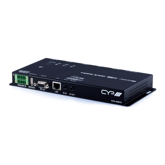
Page 10: Transmitter's Front And Rear Panels
6.2 Transmitter's Front and Rear Panels TRIGGER IN SERVICE RS-232 IR IN IR OUT TRIGGER IN: This 10 pin terminal block provides 8 trigger pins for activating functions and macros within the unit. 5V and ground pins are also provided for compatibility and use with the optional Trigger Keypad unit. -
Page 11: Receiver's Top Panel
DP IN: Connect to DisplayPort source equipment such as a PC or laptop. HDMI IN: Connect to HDMI source equipment such as a media player, game console or set-top box. VGA IN: Connect to VGA source equipment such as a PC or laptop. AUDIO IN: Connect to the stereo analog output of a device such as a CD player or PC. -
Page 12: Receiver's Front And Rear Panels
LOCK: Press and hold for 3 seconds to lock all button functions on the top panel of both the Tx and Rx. Press and hold for 3 seconds to release the lock function. The LED will be lit when the top panel is in the locked state. - Page 13 IR IN: Connect to the provided IR Extender to extend the IR control range of remotely located devices. Ensure that the remote being used is within direct line-of-sight of the IR Extender. IR OUT: Connect to the provided IR Blaster to transmit IR signals to devices within direct line-of-sight of the IR Blaster.
-
Page 14: Osd Menu
6.5 OSD Menu LEVEL 1 LEVEL 2 LEVEL 3 Output Resolution 800×600@60 1024×768@60 1280×768@60 1360×768@60 1280×800@60 1440×900@60 1280×1024@60 1400×1050@60 1680×1050@60 1600×1200@60 1920×1200@60 RB 720×480p@60 720×576p@50 1280×720p@50 1280×720p@60 1920×1080i@50 1920×1080p@50 1920×1080i@60 1920×1080p@60 3840×2160p@24 3840×2160p@25 3840×2160p@30 3840×2160p@50 Y420 3840×2160p@60 Y420 3840×2160p@50 3840×2160p@60 Bypass... - Page 15 LEVEL 1 LEVEL 2 LEVEL 3 Auto Output Colour Format Format HDMI Auto Colour Space YUV422 YUV444 Bypass Auto Colour Depth 16bit 12bit 10bit 8bit Bypass 0 ~ 100 (27) Output Image Adjust Brightness 0 ~ 100 (66) Contrast 0 ~ 100 (70) Saturation 0 ~ 100 (50) 0 ~ 100 (60)
- Page 16 LEVEL 1 LEVEL 2 LEVEL 3 Unmute Output Audio Control HDMI Audio Mute Unmute Ext Audio Mute 0 ~ 100 (80) Ext Volume Input Informational Display L/R Clock Channel Num HDMI Information Notify 5Sec Off 10Sec Off 15Sec Off 30Sec Off Always Never Input...
- Page 17 LEVEL 1 LEVEL 2 LEVEL 3 Int FHD 2CH EDID Control HDMI In Int FHD MCH Int UHD 2CH Int UHD MCH Int UHD+ 2CH Int UHD+ MCH External 1/2 User1/2/3/4 Vendor Informational Display Name MaxReso MaxBaWth MaxDepth HDR Fmt YCbCr HDCP Control HDBT In...
- Page 18 LEVEL 1 LEVEL 2 LEVEL 3 RS232 Control Local Console On/Off Baud Rate 2400 4800 7200 9600 14400 19200 38400 57600 115200 Data Length 5bit 6bit 7bit 8bit None Parity Even Stop Bit 1bit 2bit OSD Setting Auto Off 5Sec 10Sec 15Sec 30Sec...
- Page 19 LEVEL 1 LEVEL 2 LEVEL 3 Auto OSD Setting Panel Size Normal Large Gray Panel Colour Green Blue Blue Font Colour Black White Yellow Cyan Magenta FreeRun Colour Black Green Blue Default Yes/No System Setting Informational Display FW Version FW Update Yes/No Factory Reset Yes/No...
- Page 20 Notes: The OSD only provides controls for the collaboration Receiver’s functions. To control the functions of both the collaboration Transmitter and Receiver, please use the WebGUI or Telnet. Items in Bold are factory default settings. The individual functions will be introduced in the following paragraphs.
- Page 21 ► EDID Control Input EDID: When connected to a collaboration Transmitter, the “HDBT Input EDID” section will be grayed out because the Transmitter’s EDID is controlled via the WebGUI. This option is only available when connected to a “basic” HDBaseT Tx. Due to the limited OSD display space, the following have been abbreviated: Y44 = YUV 4:4:4, Y42 = YUV 4:2:2, Y40 = YUV 4:2:0.
-
Page 22: Ir Cable Pin Assignments
6.6 IR Cable Pin Assignments IR Extender IR Signal Power Ground IR Blaster Power IR Signal 6.7 RS-232 Protocol UNIT REMOTE SYSTEM Definition Definition ► ◄ Baud Rate: 115200bps Data Bits: 8 Parity Bits: None Stop Bit: 1 Flow Control: None... -
Page 23: Telnet Control
6.8 Telnet Control 6.8.1 Telnet Access Before attempting to use Telnet control, please ensure that both the unit and the PC/Laptop are connected to the same active networks. To access Telnet Click Start, type “cmd” in the search field, and In Windows 7 press Enter. - Page 24 6.8.2 Telnet/RS-232 Commands Important Notes - These Telnet/RS-232 commands are received and processed by the collaboration Transmitter, however, some commands are only available when a collaboration Receiver is also connected to the Transmitter. The section containing these special case commands has been marked with (**).
- Page 25 1. System Commands COMMAND DESCRIPTION AND PARAMETERS HELP Show the full command list. HELP N1 Show help details about command N1. N1 = {Any command name} ? Show the full command list. ? N1 Show help details about command N1. N1 = {Any command name} GET FW VER...
- Page 26 2. Input Commands COMMAND DESCRIPTION AND PARAMETERS GET IN PORT NUMBER Show the system input port number. GET IN TYPE LIST Show the system input’s type. SET IN N1 EDID N2 Assign EDID N2 to input N1. N1 = 1 ~ 4 [Input number]* Available values for N2: [Internal FHD 2CH]...
- Page 27 2. Input Commands COMMAND DESCRIPTION AND PARAMETERS GET IN N1 FORMAT Show input N1’s current format. N1 = 1 ~ 4 [Input number]* Note: Only the currently active input can be read. GET IN N1 COLOUR SPACE Show input N1’s current colour space. N1 = 1 ~ 4 [Input number]* Note: Only the currently active input can be...
- Page 28 3. Output Commands COMMAND DESCRIPTION AND PARAMETERS GET OUT PORT NUMBER Show the number of available output ports in the system. GET OUT TYPE LIST List the system’s output types. SET OUT ROUTE N1 Switch the output routing source to input N1 = 1 ~ 4 [Input number]* Note: Both outputs will display the same...
- Page 29 3. Output Commands COMMAND DESCRIPTION AND PARAMETERS SET OUT AUTO AUDIO N1 Set the output’s audio auto detection. Available values for N1: [No auto-select] [Auto-select] GET OUT AUTO AUDIO Show the current auto audio mode state. GET OUT N1 HDCP STATUS Show output N1’s current HDCP status.
- Page 30 3. Output Commands COMMAND DESCRIPTION AND PARAMETERS SET OUT N1 NAME N2 Set the name for output N1. N1 = A ~ B [Output letter] N2 = {Name} [Input name] GET OUT N1 NAME Show output N1’s name. N1 = A ~ B [Output letter] GET OUT N1 EDID DATA...
- Page 31 4. Control System Commands COMMAND DESCRIPTION AND PARAMETERS Event SET EVENT N1 NAME N2 Set the name for Event N1. N1 = 1 ~ 64 [Event number] N2 = {Name} [Event name] GET EVENT N1 NAME Show the name of Event N1. N1 = 1 ~ 64 [Event number] SET EVENT N1 N2...
- Page 32 4. Control System Commands COMMAND DESCRIPTION AND PARAMETERS GET EVENT N1 CONDITION Show Event N1’s activation condition (conditions displayed depend on the Event type). N1 = 1 ~ 64 [Event number] SET EVENT N1 MODE N2 Set Event N1 to use activation mode N2. N1 = 1 ~ 64 [Event number] Available values for N2:...
- Page 33 4. Control System Commands COMMAND DESCRIPTION AND PARAMETERS SET EVENT N1 TIMER N2 Set Event N1’s hold timer duration to N2 seconds. N1 = 1 ~ 64 [Event number] N2 = 0 ~ 65535 [Seconds] Note: Not used in all Event modes. GET EVENT N1 TIMER...
- Page 34 4. Control System Commands COMMAND DESCRIPTION AND PARAMETERS Macro SET MACRO N1 NAME N2 Set the name for macro N1. N1 = 1 ~ 64 [Macro number] N2 = {Name} [Macro name] GET MACRO N1 NAME Show macro N1’s name. N1 = 1 ~ 64 [Macro number] SET MACRO N1 ACTION N2 CMDPOOL...
- Page 35 4. Control System Commands COMMAND DESCRIPTION AND PARAMETERS SET MACRO N1 ACTION N2 INTERFACE Set the command interface for action N2 of N3 macro N1. N1 = 1 ~ 64 [Macro number] N2 = 1 ~ 16 [Action number] Available values for N3: [System command] [COM Port] [Telnet]...
- Page 36 4. Control System Commands COMMAND DESCRIPTION AND PARAMETERS SET MACRO N1 DELETE Delete macro N1. N1 = 1 ~ 64 [Macro number] SET MACRO N1 ACTION N2 DELETE Delete action N2 of macro N1. N1 = 1 ~ 64 [Macro number] N2 = 1 ~ 16 [Action number] SET MACRO N1 RUN...
- Page 37 4. Control System Commands COMMAND DESCRIPTION AND PARAMETERS GET CMDPOOL N1 DATA Show the text data contents of command N1 = 1 ~ 128 [Command number] SET CMDPOOL N1 ENDCHAR N2qw Set the termination character to send after command N1. N1 = 1 ~ 128 [Command number] Available values for N2:...
- Page 38 4. Control System Commands COMMAND DESCRIPTION AND PARAMETERS SET CTLDEVICE N1 INTERFACE N2 Set the interface for device N1. N1 = 1 ~ 16 [Device number] Available values for N2: [COM Port (On Tx)] [Telnet (On Tx)] [IR (On Tx)] [COM Port (On Rx)] [Telnet (On Rx)] [IR (On Rx)]...
- Page 39 5. Real Time Clock Commands COMMAND DESCRIPTION AND PARAMETERS SET YEAR N1 Set the real time clock year to N1. N1 = 2017 ~ 2116 [Year] GET YEAR Show the real time clock year. SET MONTH N1 Set the real time clock month to N1. N1 = 1 ~ 12 [Month] GET MONTH...
- Page 40 5. Real Time Clock Commands COMMAND DESCRIPTION AND PARAMETERS SET DATE YYYY.MM.DD Set the real time clock’s year, month and day with a single command. YYYY = 2017 ~ 2116 [Year] MM = 1 ~ 12 [Month] DD = 1 ~ 31 [Day] GET DATE...
- Page 41 5. Real Time Clock Commands COMMAND DESCRIPTION AND PARAMETERS SET CALENDAR FORMAT N1 Set the real time clock banner display format. Available values for N1: [yyyy-mm-dd hh:mm] [mm-dd-yyyy hh:mm] [dd-mm-yyyy hh:mm] [M-dd-W hh:mm] [dd-M-W hh:mm] GET CALENDAR FORMAT Show the real time clock banner display format.
- Page 42 6. Banner Commands COMMAND DESCRIPTION AND PARAMETERS SET OUT N1 BANNER N2 Enable or disable Output N1’s banner. N1 = A ~ B [Output letter] Available values for N2: [Banner disabled] [Banner enabled] GET OUT N1 BANNER Show Output N1’s banner enable state. N1 = A ~ B [Output letter] SET OUT N1 BANNER MODE N2...
- Page 43 6. Banner Commands COMMAND DESCRIPTION AND PARAMETERS SET OUT N1 BANNER FONT COLOUR N2 Set Output N1’s banner text colour. N1 = A ~ B [Output letter] Available values for N2: [Black] [White] [Red] [Green] [Blue] [Yellow] [Cyan] [Magenta] [Gray] GET OUT N1 BANNER FONT COLOUR...
- Page 44 6. Banner Commands COMMAND DESCRIPTION AND PARAMETERS SET OUT N1 BANNER TRANSPARENCY Set Output N1’s banner transparency level. N2 N1 = A ~ B [Output letter] Available values for N2: [Level 1 (opaque)] [Level 2] [Level 3] [Level 4] [Level 5] [Level 6] [Level 7] [Level 8 (transparent)]...
- Page 45 7. IR Commands COMMAND DESCRIPTION AND PARAMETERS SET IR N1 LEARN N2 Initiate the IR learning function on IR Input N1. The captured IR code will be written to command slot N2. Available values for N1: [IR input on Tx] [IR input on Rx] N2 = 1 ~ 128 [Command number]...
- Page 46 8. Collaboration Receiver Commands** COMMAND DESCRIPTION AND PARAMETERS Output SET OUT N1 TIMING N2 Set the output timing for Rx Output N1. N1 = B [HDMI Out on the Rx] Available values for N2: [Bypass] [800×600@60] [1024×768@60] [1280×768@60] [1360×768@60] [1280×800@60] [1440×900@60] [1280×1024@60] [1400×1050@60]...
- Page 47 8. Collaboration Receiver Commands** COMMAND DESCRIPTION AND PARAMETERS GET OUT N1 TIMING Show the current output timing for Rx Output N1. N1 = B [HDMI Out on the Rx] SET OUT N1 COLOUR SPACE N2 Set Rx Output N1’s colour space. N1 = B [HDMI Out on the Rx] Available values for N2:...
- Page 48 8. Collaboration Receiver Commands** COMMAND DESCRIPTION AND PARAMETERS SET OUT N1 FORMAT N2 Set Rx Output N1’s video format. N1 = B [HDMI Out on the Rx] Available values for N2: [DVI Mode] [HDMI Mode] [Auto Detect] GET OUT N1 FORMAT Show Rx Output N1’s video format.
- Page 49 8. Collaboration Receiver Commands** COMMAND DESCRIPTION AND PARAMETERS GET OUT N1 SATURATION Show Rx Output N1’s saturation. N1 = B [HDMI Out on the Rx] SET OUT N1 HUE N2 Set Rx Output N1’s hue. N1 = B [HDMI Out on the Rx] N2 = 0 ~ 100 [Hue level] Note: Only active when the output timing is...
- Page 50 8. Collaboration Receiver Commands** COMMAND DESCRIPTION AND PARAMETERS Audio SET AUDIO OUT MUTE N1 Mute or un-mute the Rx’s external stereo analog audio output. Available values for N1: [Un-mute] [Mute] Note: The stereo analog audio output will always be muted with bitstream audio sources.
- Page 51 9. User EDID Commands COMMAND DESCRIPTION AND PARAMETERS GET USER EDID NUMBER List the number of User EDID slots. GET USER N1 EDID DATA Show the ASCII HEX data from User EDID N1. N1 = 1 ~ 4 [User EDID number] GET USER N1 EDID INFORMATION...
-
Page 52: Webgui Control
6.9 WebGUI Control 6.9.1 Device Discovery APP Please obtain the Device Discovery software from your authorised dealer and save it in a directory where you can easily find it. Connect the unit and your PC/laptop to the same active network and execute the Device Discovery software. - Page 53 6.9.2 WebGUI Control Page After connecting to the WebGUI’s address in a web browser, the login screen will appear. Please enter the appropriate user name and password then click “Submit” to log in. Note: The default user name and password is “admin”. On the left side of the browser you will see the following menu tabs where all primary functions of the paired collaboration Transmitter and Receiver are controllable via the built in WebGUI: A/V Switch, EDID,...
- Page 54 1. Audio/Video Switch This tab provides A/V routing control, A/V mute controls, and I/O renaming options. To assign a new video or audio route, please click the button of the Output you wish to send video/audio to on the left and then click on the button of the preferred Input port (video or audio) on the right.
- Page 55 Output HDMI/HDBaseT - A/B: Buttons for selecting the Output (A or B) to route video or audio sources to. - Name: Displays the name for the Output. Click the icon to edit the Output’s name. - Video: Displays the Input that is currently routed to the Output. - Audio: Displays the audio embedding mode for the Output.
- Page 56 2. EDID This collaboration Transmitter provides the option of six internal EDIDs, four customer uploaded EDIDs, and two sink sourced EDIDs that can be assigned to each input port individually. All EDIDs are available for download and saving to a PC. Important details from each EDID may also be displayed.
- Page 57 User EDID - Drop-down Menu: Drop-down to select a User EDID for upload, download or to view its information details. - Upload: Click to upload a previously saved EDID file (*.bin) from the PC to the selected User EDID slot. - Download: Click to download the selected EDID file (*.bin) to the PC.
- Page 58 3. Banner This tab provides control over the content, format and activation of the OSD banner information displayed on both outputs. Click the Enable switch to enable/disable the corresponding OSD banner. Click the icon to open the corresponding Banner Edit page.
- Page 59 - Mode: Select the OSD banner display text content. - Font Colour: Select the OSD banner font colour. - Background Colour: Select the OSD banner background colour. - Background Transparency: Select the OSD banner background transparency level. The range is from 1 (opaque) to 8 (transparent). - User Text: Enter customised banner text (only available when “User Text”...
- Page 60 4. Collaboration This tab provides controls for the Output B scaler and other features implemented within the collaboration Receiver including output resolution, audio volume, proc-amp functions, and relay control. Note: If a non-collaboration Receiver is connected, functions on this tab will be disabled.
- Page 61 Audio Provides control over the analog audio output on the Receiver. Click the Mute switch to enable or disable analog audio output. Move the Volume slider to control the analog output volume. Note: Digital audio output via HDMI cannot be adjusted. Firmware Upgrade Provides a way to update the Receiver’s firmware.
- Page 62 5. Event Book The Event Book tab provides a way to view the details of all existing Events, both active and inactive, that are saved in the unit. The conditions to activate an Event and the actions that are performed once the event has been triggered are listed in an easy to read natural English format.
- Page 63 Note: Before creating new Events, please be sure that all required macros, commands and devices have already been defined. - Active: Displays the active state of each Event. Events that have Active set to “OFF” cannot be triggered. - Event Name: Displays each Event’s name. - Event Type: Displays the type of trigger/interface that is being watched to activate an Event.
- Page 64 - Toggle: The Event runs alternating macros (a single time for each trigger) each time the Event is triggered. - Macro: Displays the name of the macro to run when the Event is triggered. - Edit/New: Click the “Edit” or “New” button to open the Event Edit window and edit an existing Event, or create a new one.
- Page 65 7. Macro The “Macro” tab provides a way to create, edit, run and delete macros. Up to 64 macros can be stored in the unit, and each macro can contain up to 16 individual actions with user defined delays (in milliseconds) between each command’s execution.
- Page 66 Macro Edit Window Click the “Add” button to add a new macro action. - Command Name: Displays the name of the command used in each action step of the macro. - Interface: Displays the interface that the command data will be transmitted on.
- Page 67 Interface Edit Window The “Delay(ms)” setting is the length of time to wait before sending the next action and is set in milliseconds. Click on “Save Change” to confirm the settings. Note: It is strongly suggested to not set a delay time less than 100ms for system commands or less than 500ms for Telnet/Serial commands to ensure that the command is properly received and executed before the next command is sent.
- Page 68 8. Command Click on the “Command” tab to create, edit or delete commands. Up to 128 individual commands can be stored in the command pool. Note: The Command tab is not available when the user is logged in using an “Operator”...
- Page 69 9. Device Click on the “Device” tab to add/remove common, or multiple-use device interfaces to make setting up macros which repeatedly use the same interfaces much easier. There are 4 types of device interfaces (either Remote or Local) that can be defined for easy use with a total of 16 stored. The name of each device can be up to 32 characters long (spaces are not allowed).
- Page 70 10. Network Click on the “Network” tab to make changes to various network settings. From this tab you can change the WebGUI IP configuration, login account and login timeout settings. IP Configuration This section allows for configuration of the Ethernet settings of the unit. The IP mode may be switched between DHCP or Static IP.
- Page 71 Web Login Account Click the drop-down to select the user account number to edit (out of a total of 4 available users). After selecting an account, click the “New/Edit” button to set or modify the username, password, and access privileges (Administrator or Operator).
- Page 72 11. System This tab provides access to control a number of system configuration controls including saving and restoring the system configuration, performing a factory reset, rebooting the system, updating the firmware of the collaboration Transmitter, setting the system’s time & date, and displaying the unit’s serial number.
- Page 73 Firmware Upgrade Provides a way to update the Transmitter’s firmware. Click “Choose File” to select the firmware update file from the local PC (*.bin format). After selecting an appropriate file, click the “Upgrade” button to begin the update process. Serial Number Displays the serial number of the unit.
-
Page 74: Connection Diagram
7. CONNECTION DIAGRAM Laptop Media Player RS-232 DisplayPort HDMI Stereo Input Input Input Input Audio Input IR In/Out HDMI 1.5m Output 60° 60° UHDTV CAT 5e/6/7 OUT HDMI OUT DP IN HDMI IN VGA IN AUDIO IN Trigger 7 0 M Multi-Format 4K UHD+ over HDBaseT Tx TRIGGER IN SERVICE... -
Page 75: Specifications
8. SPECIFICATIONS 8.1 Technical Specifications Transmitter Video Bandwidth HDMI: 600MHz/18Gbps HDBaseT: 340MHz/10.2Gbps Input Ports 1×HDMI 1×DisplayPort 1×VGA 1×3.5mm (Stereo Audio) Output Ports 1×HDMI 1×Cat.5e/6/7 Control Interfaces 1×IR Blaster (3.5mm) 1×IR Extender (3.5mm) 1×RS-232 (9-pin D-sub) 1×LAN (RJ45) HDMI Cable Length 10m (1080p@60Hz, 12-bit) 3m (4K@60Hz, 4:4:4, 8-bit) CAT5e/6 Cable Length... - Page 76 Weight 420g Chassis Material Metal Silkscreen Colour Black Operating Temperature 0˚C - 40˚C/32˚F - 104˚F Storage Temperature −20˚C - 60˚C/−4˚F - 140˚F Relative Humidity 20 - 90% RH (Non-condensing) Power Consumption Receiver Video Bandwidth HDMI: 600MHz/18Gbps HDBaseT: 340MHz/10.2Gbps Input Ports 1×HDMI 1×Cat.5e/6/7 Output Ports...
- Page 77 ESD Protection Human Body Model: ±8kV (Air Discharge) ±4kV (Contact Discharge) Dimensions 231.5mm×25mm×108mm (W×H×D) [Case Only] 231.5mm×25mm×120mm (W×H×D) [All Inclusive] Weight 430g Chassis Material Metal Silkscreen Colour Black Operating Temperature 0˚C - 40˚C/32˚F - 104˚F Storage Temperature −20˚C - 60˚C/−4˚F - 140˚F Relative Humidity 20 - 90% RH (Non-condensing) Power Consumption...
-
Page 78: Video Specifications
8.2 Video Specifications 8.2.1 Transmitter's Resolutions Input Output Transmitter's Supported Resolutions (Hz) HDMI HDMI HDBT 640×480p@60 640×480p@72 640×480p@75 640×480p@85 720×400p@70 ... - Page 79 Input Output Transmitter's Supported Resolutions (Hz) HDMI HDMI HDBT 1280×720p@24 1280×720p@25 1280×720p@29 1280×720p@30 1280×720p@50 1280×720p@59 1280×720p@60 ...
- Page 80 Input Output Transmitter's Supported Resolutions (Hz) HDMI HDMI HDBT 1440×900p@60 (RB) 1440×900p@75 1600×900p@60 (RB) 1600×1200p@60 1600×1200p@65 1600×1200p@70 1600×1200p@75 ...
- Page 81 Input Output Transmitter's Supported Resolutions (Hz) HDMI HDMI HDBT 2048×1080p@50 2048×1080p@59 2048×1080p@60 3840×2160p@23 3840×2160p@24 3840×2160p@25 3840×2160p@29 ...
- Page 82 8.2.2 Receiver's Resolutions Input Output Receiver's Supported Bypass Scaled Resolutions (Hz) HDBT HDMI HDMI HDMI 640×480p@60 640×480p@72 640×480p@75 640×480p@85 720×400p@70 720×400p@85 720×480i@59 ...
- Page 83 Input Output Receiver's Supported Bypass Scaled Resolutions (Hz) HDBT HDMI HDMI HDMI 1280×720p@29 1280×720p@30 1280×720p@50 1280×720p@59 1280×720p@60 1280×768p@60 1280×768p@60 (RB) ...
- Page 84 Input Output Receiver's Supported Bypass Scaled Resolutions (Hz) HDBT HDMI HDMI HDMI 1600×1200p@60 1600×1200p@65 1600×1200p@70 1600×1200p@75 1600×1200p@85 1680×1050p@60 1680×1050p@60 (RB) ...
- Page 85 Input Output Receiver's Supported Bypass Scaled Resolutions (Hz) HDBT HDMI HDMI HDMI 3840×2160p@23 3840×2160p@24 3840×2160p@25 3840×2160p@29 3840×2160p@30 3840×2160p@50 3840×2160p@59 ...
- Page 86 8.2.3 Colour Space Conversions Input Output Colour Colour Resolution (Hz) Space Bit Depth Space Bit Depth 4K@23/24/25/29/30 YUV 4:4:4 YUV 4:4:4 YUV 4:4:4 YUV 4:4:4 YUV 4:4:4 YUV 4:4:4 4K@50/59/60 YUV 4:2:0 YUV 4:4:4 YUV 4:2:0 YUV 4:2:0 YUV 4:2:0 YUV 4:2:0 YUV 4:2:0 YUV 4:2:0...
-
Page 87: Application Notes
8.3 Application Notes ► The unit’s default IP address is 192.168.1.50. ► 4K UHD sources or equivalently high-bandwidth signals require an appropriate compatible display and Premium High Speed HDMI or certified DisplayPort 1.2 cables in order to achieve the best image quality. -
Page 88: Acronyms
9. ACRONYMS ACRONYM COMPLETE TERM Cat.5e Category 5 (enhanced) Cable Cat.6 Category 6 Cable Cat.7 Category 7 Cable Consumer Electronics Control Command Line Interface DisplayPort Digital Visual Interface EDID Extended Display Identification Data Graphical User Interface High-Definition HDCP High-bandwidth Digital Content Protection HDMI High-Definition Multimedia Interface High Dynamic Range... - Page 92 CYP (UK) Ltd., Unit 7, Shepperton Business Park, Govett Avenue, Shepperton, Middlesex, TW17 8BA Tel: +44 (0) 20 3137 9180 | Fax: +44 (0) 20 3137 6279 Email: sales@cypeurope.com www.cypeurope.com v1.00...
Need help?
Do you have a question about the PUV-1650TX and is the answer not in the manual?
Questions and answers