Table of Contents
Advertisement
Quick Links
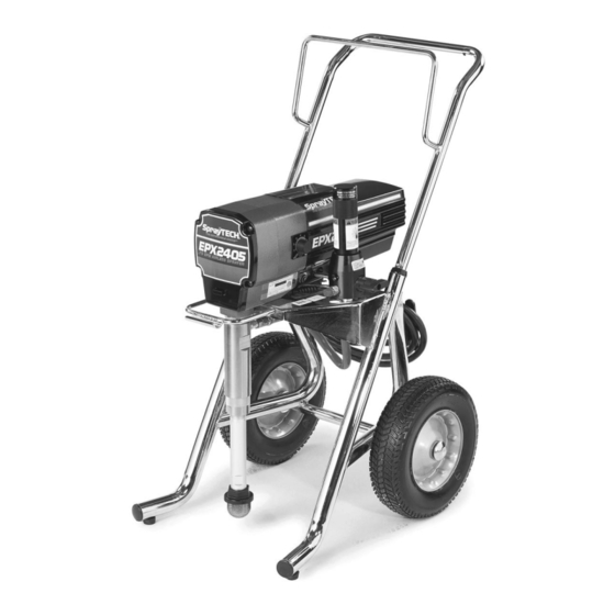
EPX2405
Piston Pum p
Printed in the U. S. A.
Owner's Manual
Model Numbers:
0507008 Upright Cart
0507018 Low Boy Cart
SprayTECH
1770 Fernbrook Lane
Minneapolis, MN 55447
Technical Assistance: 1-800-292-4637
Order Entry: 1-800-443-4500
ww w.s pray t e chi nc . c o m
0302 © 2002 SprayTECH. All rights reserved. Form No. 0507836A
Fax: 1-800-525-9501
Advertisement
Table of Contents

Related Manuals for SprayTECH EPX2405


Summary of Contents for SprayTECH EPX2405
- Page 1 1770 Fernbrook Lane Minneapolis, MN 55447 Technical Assistance: 1-800-292-4637 Order Entry: 1-800-443-4500 Fax: 1-800-525-9501 ww w.s pray t e chi nc . c o m Printed in the U. S. A. 0302 © 2002 SprayTECH. All rights reserved. Form No. 0507836A...
-
Page 2: Table Of Contents
• NEVER aim the gun at any part of the body. • NEVER allow any part of the body to touch the fluid stream. DO NOT allow body to touch a leak in the fluid hose. © SprayTECH. All rights reserved. - Page 3 3300PSI/228 BAR. • Do not spray outdoors on windy days. • Wear clothing to keep paint off skin and hair. • Always unplug cord from outlet before working on equipment. © SprayTECH. All rights reserved.
-
Page 4: General Description
NOTE: Make sure that the spray gun does not have a minimum. tip or tip guard installed. 7. Plug the power cord into a properly grounded outlet at 7. Move the PRIME/SPRAY valve to the SPRAY position. least 25’ from the spray area. © SprayTECH. All rights reserved. -
Page 5: Painting
12. Lock the gun by turning the gun trigger lock to the locked position. 13. Turn the unit off by moving the pressure control knob to the “0” position. © SprayTECH. All rights reserved. -
Page 6: Spraying
• Area must be free of flammable vapors. • Follow all cleanup instructions. CAUTION The sprayer, hose, and gun should be cleaned thoroughly after daily use. Failure to do so permits material to build up, seriously affecting the performance of the unit. © SprayTECH. All rights reserved. -
Page 7: Maintenance
Always contact the supplier of solvents WARNING for recommendations. 4. If you have any further questions concerning your SprayTECH Airless Sprayer, call SprayTECH: Ground the gun by holding it against the edge of the metal container while Technical Service........1-800-292-4637 flushing. -
Page 8: Replacing The Filters
Filter Electrostatic discharge (ESD) potential could cause spring. Body damage to electronic control. Use SprayTECH ESD wrist 3. Inspect the filter. Based on strap P/N 0507958 or equivalent when working on inspection, clean or replace the electronic control with electronic cover removed. -
Page 9: Replacing The Gears
Motor Shroud 17. Secure the motor shroud with the four motor shroud screws. Grommet Front End Bell Transducer Assembly Armature Gear 1st Stage Gear Mounting Plate 2nd Stage Gear Front Gear Box Assembly Housing Gasket © SprayTECH. All rights reserved. -
Page 10: Servicing The Fluid Section
29. Place the cylinder upright in a vise by clamping on the Housing wrench flats. 30. Locate the new upper and lower packings. Soak the new leather packings in linseed oil for 5 minutes. Do not over- soak. © SprayTECH. All rights reserved. - Page 11 46. Thread the siphon tube/suction set into the inlet valve and tighten securely. Make sure to wrap the threads on the down tube/siphon hose adapter with PTFE tape before assembly. 47. Replace the return hose into the clamp on the siphon tube. © SprayTECH. All rights reserved.
-
Page 12: Troubleshooting
4. Faulty or loose wiring. 4. Inspect or take to a SprayTECH authorized service center. 5. Excessive motor temperature. 5. Allow motor to cool. - Page 13 The unit lacks power. 1. The pressure adjustment is too low. 1. Rotate the pressure control knob clockwise to increase the pressure setting. 2. Improper voltage supply. 2. Reconnect the input voltage for 120V AC. © SprayTECH. All rights reserved.
- Page 15 • Tous les accessoires doivent être homologués pour une pression égale ou supérieure à 3 200 lb/po2 / 228BAR. Cela s'applique, entre autres, aux têtes de pulvérisation, aux accessoires du pistolet et aux flexibles. Français © SprayTECH. Tous droits réservés.
- Page 16 à une pression égale ou supérieure à 3 200 lb/po2 / 228BAR. • Ne jamais pulvériser lorsqu'il vente. • Porter des vêtements pour protéger la peau et les cheveux contre tout contact avec la peinture. Français © SprayTECH. Tous droits réservés.
- Page 17 Consulte el manual del motor • Todos los accesorios deben tener una capacidad de 3300 para obtener información completa de seguridad. lb/pulg2 / 228BAR o mayor. Esto incluye las boquillas de atomizador, pistolas, extensiones y mangueras. Español © SprayTECH. Todos los derechos reservados.
- Page 18 3300 lb/pulg2 / 228 BAR o mayor. • No atomice en días con viento. • Use ropa que evite el contacto de la pintura con la piel y el cabello. Español © SprayTECH. Todos los derechos reservados.
-
Page 19: Main Assembly
Jam nut ............1 0507690 PRIME/SPRAY valve assembly....1 0507163 Fluid section assembly ......1 5000527 Outlet fitting..........1 0507798 Siphon tube..........1 0507671 Fitting ............1 0507783 Hose clamp..........1 0507793 Fitting ............1 5006536 Inlet screen ..........1 0507387 Hose (not shown) ........1 © SprayTECH. All rights reserved. -
Page 20: Drive Assembly
Motor shroud w/labels ........1 0507754 Relay............1 0507961 Wire cover, 7” (not shown) ......1 0507750 Screw............1 0507962 Wire assembly (not shown) ......1 0507753 Circuit breaker ..........1 NOTE: All electrical work should be performed by a Spraytech authorized service center. © SprayTECH. All rights reserved. -
Page 21: Fluid Section Assembly
Inlet valve housing........1 0507229 Piston assembly (includes items 13–19) ..1 0507923 Repacking kit (includes items 2–6, 8–12, 14, 16, 17, 21, 23, 24, and 25) Peak Install all lower packings with peak of "V" packing pointing down. © SprayTECH. All rights reserved. -
Page 22: Upright Cart Assembly
PRIME/SPRAY valve assembly....1 0294534 Spacer ............4 0507765 Cart weldment (includes items 8–10) ..1 9885571 Plug.............2 13538 Bumper ............2 54458 Screw............2 0295608 Screw............4 0295606 Washer............4 0507774 Screw............4 0507655 Cord wrap ...........2 0507379 Wheel............2 9890104 Cap .............2 © SprayTECH. All rights reserved. -
Page 23: Low Boy Cart Assembly
Handle assembly 0294534 Wheel spacer..........2 (includes items 1–3, 5, 9, and 10) ....1 0278373 Wheel............2 0295610 Roll pin............2 9890104 Cap .............2 0295617 Plug.............2 ---------- Cart weldment (includes items 6 and 8)..1 0507955 Screw............1 5006854 Plug.............2 © SprayTECH. All rights reserved. -
Page 24: Electrical Schematic
0507737 Wire Assembly Gear Housing 0507962 Potentiometer Assy BLACK ORANGE 0507759 Electronic GREEN Control Assy Motor BLACK WHITE Relay 0507754 WHITE BLACK/RED/WHITE NOTE: All electrical work should be performed by a SprayTECH authorized service center. © SprayTECH. All rights reserved. -
Page 25: Limited Warranty
SprayTECH’s option, refund to the original purchaser the full purchase price for the product in exchange for the return of that product. However, SprayTECH will not replace or repair any fluid pump component on account of wear more than once during the two year warranty period.
Need help?
Do you have a question about the EPX2405 and is the answer not in the manual?
Questions and answers