Siemens Ruggedcom RMC30 Technical Guidance Notes
Ethernet interface
Hide thumbs
Also See for Ruggedcom RMC30:
- Installation manual (36 pages) ,
- Installation manual (40 pages)
Table of Contents
Advertisement
Quick Links
D
OCUMENTATION
All referenced documents can be provided on request to Siemens Protection Devices Ltd. Tel No. +44
(0)191 401 5555. They can also be found on our website at www.reyrolle-protection.com.
The copyright and other intellectual property rights in this document, and in any model or article produced from it (and including
any registered or unregistered design rights) are the property of Siemens Protection Devices Limited. No part of this document
shall be reproduced or modified or stored in another form, in any data retrieval system, without the permission of Siemens
Protection Devices Limited, nor shall any model or article be reproduced from this document unless Siemens Protection Devices
Limited consent.
While the information and guidance given in this document is believed to be correct, no liability shall be accepted for any loss or
damage caused by any error or omission, whether such error or omission is the result of negligence or any other cause. Any
and all such liability is disclaimed.
©2007 Siemens Protection Devices Limited
Technical Guidance Notes
Ethernet Interface
Ruggedcom RMC30
Technical Guidance Notes
P issue 2007/12
Advertisement
Table of Contents

Related Manuals for Siemens Ruggedcom RMC30


Summary of Contents for Siemens Ruggedcom RMC30
-
Page 1: Documentation
Siemens Protection Devices Limited. No part of this document shall be reproduced or modified or stored in another form, in any data retrieval system, without the permission of Siemens Protection Devices Limited, nor shall any model or article be reproduced from this document unless Siemens Protection Devices Limited consent. -
Page 2: Document Release History
Technical Guidance Notes OCUMENT ELEASE ISTORY This document is issue 2007/12. The list of revisions up to and including this issue is: 2007/12 First issue for Review Page 2 of 29 ©2007 Siemens Protection Devices Limited... -
Page 3: Table Of Contents
3.1 Configure RMC30 IP Address....................9 3.2 Configure RMC30 MODBUS Parameters................13 3.3 Configure RMC30 DNP3 Parameters..................22 3.4 Configure RMC30 Tunnel Parameters ...................26 Section 4: Definitions...........................27 4.1 Introduction ..........................27 Section 5: Glossary..........................28 Section 6: Appendix..........................29 ©2007 Siemens Protection Devices Limited Page 3 of 29... - Page 4 Figure 27 – RMC30 Browser Interface – IED DNP3 Device Entry............26 Figure 28 – RMC30 Browser Interface – Serial Port for Raw Socket ............26 Figure 29 – Rear Terminals for E8 case (5CT/4VT) ................29 Page 4 of 29 ©2007 Siemens Protection Devices Limited...
-
Page 5: Section 1: Introduction
Technical Guidance Notes Section 1: Introduction This note describes the connection of the RUGGEDCOM RMC30 external Ethernet interface to the RS485 port of Reyrolle Relays. The new generation of Reyrolle relays support the DNP3 communications standard, in addition to MODBUS and IEC60870-5-103 provided previously. Each communications port allows the user to select a protocol, independent of the other ports, via a setting accessed through the Relay’s fascia. -
Page 6: Section 2: Physical Connection
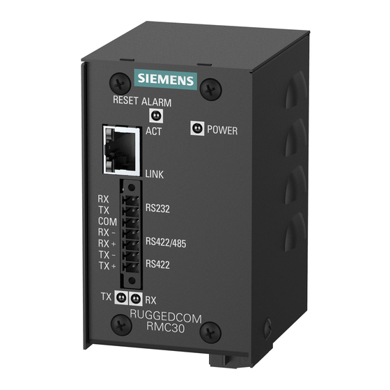
Connect the Serial Port terminals to the Relay. For an RS485 2 wire connection connect the –Rx terminal of the Phoenix connector to A on the Relay, and the +Rx terminal to B. Page 6 of 29 ©2007 Siemens Protection Devices Limited... -
Page 7: Rs232 Interface
Ethernet connection, as shown below. Figure 3 – RMC30 RS232 connection 2.2.3 Ethernet Interface Connect the RMS30 to the network using a standard RJ45 Ethernet cable. ©2007 Siemens Protection Devices Limited Page 7 of 29... -
Page 8: Power Supply
Technical Guidance Notes 2.2.4 Power Supply Connect a suitable PSU to the RMC30. Figure 4 – RMC30 Bottom View Showing Power Supply Connection Page 8 of 29 ©2007 Siemens Protection Devices Limited... -
Page 9: Section 3: Configuration Of Rmc30 Device
8 bit data and VT100 emulation. While holding down CTRL+Z on the PC keyboard power up the RMC30. After a short while you will be presented with a screen as follows. Figure 5 – RMC30 Confirm Screen Type yes to continue ©2007 Siemens Protection Devices Limited Page 9 of 29... -
Page 10: Figure 6 - Rmc30 Boot Screen
Figure 8 – RMC30 Example Login Screen The main menu screen is displayed. Use the arrow keys (←↑↓→) to navigate menus, Enter to enter a menu and Escape to leave it and return to the previous level. Page 10 of 29 ©2007 Siemens Protection Devices Limited... -
Page 11: Figure 9 - Rmc30 Main Menu
Technical Guidance Notes Figure 9 – RMC30 Main Menu Press return to open the Administration menu. Figure 10 – RMC30 Administration Menu Press return to open the Configure IP Interfaces menu. ©2007 Siemens Protection Devices Limited Page 11 of 29... -
Page 12: Figure 11 - Rmc30 Ip Interfaces Menu
Figure 12 – RMC30 IP Apply Address Changed For the purposes of this test the IP address used is 169.254.199.24. Press the return key to accept the new address, and then CTRL+A to apply it. Page 12 of 29 ©2007 Siemens Protection Devices Limited... -
Page 13: Configure Rmc30 Modbus Parameters
To configure parameters, start up a web browser and attach to the IP address set in section 3.1, in this example 169.254.199.24. You will be presented with the initial page as shown below. ©2007 Siemens Protection Devices Limited Page 13 of 29... -
Page 14: Figure 15 - Rmc30 Browser Interface - Initial Page
Figure 15 – RMC30 Browser Interface – Initial Page First, login to the device, again using “admin” as both the User Name and Password. After logging in you will be presented with the main menu page. Page 14 of 29 ©2007 Siemens Protection Devices Limited... -
Page 15: Figure 16 - Rmc30 Browser Interface - Main Menu
Technical Guidance Notes Figure 16 – RMC30 Browser Interface – Main Menu Click on Serial Protocols to open the tree. ©2007 Siemens Protection Devices Limited Page 15 of 29... -
Page 16: Figure 17 - Rmc30 Browser Interface - Serial Protocols Menu
Technical Guidance Notes Figure 17 – RMC30 Browser Interface – Serial Protocols Menu Click on Configure Serial Ports to open the page. Page 16 of 29 ©2007 Siemens Protection Devices Limited... -
Page 17: Figure 18 - Rmc30 Browser Interface - Serial Ports Configuration Page
Technical Guidance Notes Figure 18 – RMC30 Browser Interface – Serial Ports Configuration Page Click on 1 to configure port 1. ©2007 Siemens Protection Devices Limited Page 17 of 29... -
Page 18: Figure 19 - Rmc30 Browser Interface - Serial Port 1 Configuration Page
Click Apply to save the changes, note the confirmation message. Click Back to return to the Main Menu. From the Main Menu Serial Protocols tree click Configure Device Address Table to open the page. Page 18 of 29 ©2007 Siemens Protection Devices Limited... -
Page 19: Figure 20 - Rmc30 Browser Interface - Empty Device Address Table Page
Technical Guidance Notes Figure 20 – RMC30 Browser Interface – Empty Device Address Table Page Click Insert Record to open the editor page. ©2007 Siemens Protection Devices Limited Page 19 of 29... -
Page 20: Figure 21 - Rmc30 Browser Interface - Device Address Editor Page
1, the RS422/485 port we configured earlier. Leaving the remote IP address field blank will cause the address we set earlier to be used. Click apply to save the settings, then back to return to the table. Page 20 of 29 ©2007 Siemens Protection Devices Limited... -
Page 21: Figure 22 - Rmc30 Browser Interface -Populated Device Address Table Page
MODBUS client port number of 502. If you need to change this parameter open the Configure Protocols branch, see Figure 17 – RMC30 Browser Interface – Serial Protocols Menu, select MODBUS client and change the IP Port number. ©2007 Siemens Protection Devices Limited Page 21 of 29... -
Page 22: Configure Rmc30 Dnp3 Parameters
Protocols page, refer back to Figure 17 – RMC30 Browser Interface – Serial Protocols Menu. Then click Serial ports. Set the protocol to be DNP3 and the baud rate, parity etc. to be those you intend to use with the relay, see example below. Page 22 of 29 ©2007 Siemens Protection Devices Limited... -
Page 23: Figure 24 - Rmc30 Browser Interface - Serial Port For Dnp3
You need to add two devices, one for the PC (or Master) and one for the IED device. In the example shown below I have given the PC address 3 and used its IP address (169.254.199.21) when adding to the table. ©2007 Siemens Protection Devices Limited Page 23 of 29... -
Page 24: Figure 25 - Rmc30 Browser Interface - Pc Dnp3 Device Entry
Figure 25 – RMC30 Browser Interface – PC DNP3 Device Entry The IED was connected to communications port 1 (RS485).The address on the IED was set to 4. The IP address is that of the RMC30, in this instance 169.254.199.24. Page 24 of 29 ©2007 Siemens Protection Devices Limited... -
Page 25: Figure 26 - Rmc30 Browser Interface - Ied Dnp3 Device Entry
Technical Guidance Notes Figure 26 – RMC30 Browser Interface – IED DNP3 Device Entry Click Back and the table should now look some thing like the one shown below in Figure 27. ©2007 Siemens Protection Devices Limited Page 25 of 29... -
Page 26: Configure Rmc30 Tunnel Parameters
Raw Socket client port number of 50001. If you need to change this parameter open the Configure Protocols branch, see Figure 17 – RMC30 Browser Interface – Serial Protocols Menu, select Raw Socket and change the Loc Port number. Page 26 of 29 ©2007 Siemens Protection Devices Limited... -
Page 27: Section 4: Definitions
Events; Measurands; Commands etc, refer to the Data Communications section of the relevant product manual. The information regarding the RMC30 device was taken from the following document Rugged Operating System v3.2 User Guide ©2007 Siemens Protection Devices Limited Page 27 of 29... -
Page 28: Section 5: Glossary
Bit (logical 0) sent to signify the start of a byte during data transmission. Stop Bit Bit (logical 1) sent to signify the end Universal Serial Bus standard for the transfer of data. Page 28 of 29 ©2007 Siemens Protection Devices Limited... -
Page 29: Section 6: Appendix
Technical Guidance Notes Section 6: Appendix Figure 29 – Rear Terminals for E8 case (5CT/4VT) ©2007 Siemens Protection Devices Limited Page 29 of 29...
Need help?
Do you have a question about the Ruggedcom RMC30 and is the answer not in the manual?
Questions and answers