Table of Contents
Advertisement
Quick Links
Installation Instructions
Model RNI
Remote Network Interface
INTRODUCTION
PRE-INSTALLATION
P/N 315-033420-4
The SIEMENS Model RNI allows for the remote
installation of the PMI-REM, SSD-C-REM (on HNET)
and the LCM-8/SCM-8/FCM-6/SIM-16/OCM-16 (on
CAN) modules.
The HNET can be wired either Style 4 or Style 7 . The
CAN network may only be wired Style 4. The RNI
may be placed in the middle or at the end of either
the HNET or CAN networks. A 24VDC input is also
required. This can be obtained from the PSC-12
power limited output (TB3) or any UL/ULC regulated,
power limited power supply listed for fire protective
signaling use.
The RNI mounts in the rear of either the REMBOX2
or REMBOX4 enclosures. The RNI provides terminal
blocks for all field wiring connections. Internal
connections are made to plug in connectors specifi-
cally provided for each of the installed modules.
The HNET and the CAN networks can be used
simultaneously.
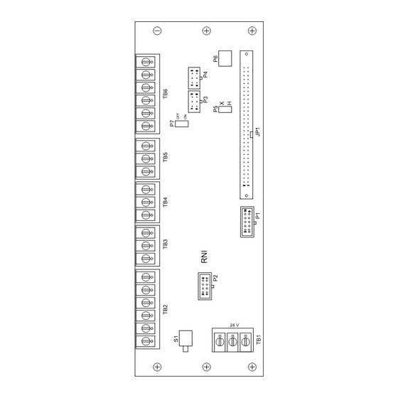
P7 enables or disables an audible device similar to the CSB. This audible sounds
whenever a switch is pressed on either the SCM-8 or the FCM-6. If this is not desired
the audible can be silenced by changing the jumper installed on P7 to positions 2 and
3. P7 is configured in the factory (positions 1 and 2) to have the audible active.
S1 is used to terminate the HNET. If the RNI is installed at the end of an HNET
network S1 must be set to the ON position. If the RNI is in the middle of the HNET
set S1 to the OFF position.
P5 must be set to the HNET (H) position.
Figure 1
RNI Remote Network
Interface
Siemens Building T T T T T ec
Siemens Building
Siemens Building
Siemens Building
Siemens Building
24 V
ec
echnologies
ec
hnologies
hnologies
hnologies
ec
hnologies
Fire S
Fire Safety
Fire S
Fire S
Fire S
afety
afety
afety
afety
Advertisement
Table of Contents

Related Manuals for Siemens RNI


Summary of Contents for Siemens RNI
-
Page 1: Installation Instructions
S1 is used to terminate the HNET. If the RNI is installed at the end of an HNET network S1 must be set to the ON position. If the RNI is in the middle of the HNET set S1 to the OFF position. - Page 2 A 24 inch long 60 wire cable, P/N 555-133998 (shipped with the PMI-REM), connects the RNI to the PMI-REM. Connect one end of the cable to JP1 on the RNI and the other end of the cable to JP3 on the PMI-REM. Be sure that the PMI-REM address agrees with the ZEUS configuration.
- Page 3 CAN – SHIELD FROM PSC-12 DO NOT CAN + C– C– CCL (SUPPLIED WITH THE RNI) DO NOT NOTES: 1. 24 AWG min., 12 AWG max. 2. 15 ohms max. for CAN network. 3. Use twisted pair or twisted †...
- Page 4 Figure 7 Connecting CAN In The Middle Of The Network Connecting The Optional Connect the HTSW-1 (required for UL1076) to P6 on the RNI using the connector HTSW-1 Tamper Switch supplied with HTSW-1. Refer to the REMBOX Installation Instructions, P/N 315- 033772 and the HTSW-1 Installation Instructions, P/N 315-033350.
- Page 5 Check the setting of S1. If the RNI is at the end of the HNET is must be set to on. If the RNI is in the middle of the HNET it must be set to off. If the HNET is not used the position of S1 does not matter.
- Page 6 For CE applications in Cerberus E100 systems refer to Installation Instruction A24205-A334-B844 (English) or A24205-A334-A844 (German). Siemens Building Technologies, Inc. Siemens Building Technologies, Ltd. Siemens Gebäudesicherheit 8 Fernwood Road 2 Kenview Boulevard GmbH & Co. oHG Florham Park, New Jersey 07932 Brampton, Ontario L6T 5E4 CN D-80930 München...
Need help?
Do you have a question about the RNI and is the answer not in the manual?
Questions and answers