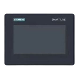
Siemens Smart 700 IE V4 Operating Instructions Manual

Siemens Smart 700 IE V4 Operating Instructions Manual

Simatic hmi
Table of Contents

Advertisement

Quick Links

Smart 700 IE V4, Smart 1000 IE V4
SIMATIC HMI
HMI devices
Smart 700 IE V4, Smart 1000 IE V4
Operating Instructions
01/2023
A5E51638950-AB
Preface
Overview
Safety instructions
Mounting and connecting
Operating the device
Configuring the device
Commissioning a project
Maintenance and care
Technical specifications
Technical Support
Abbreviations
1
2
3
4
5
6
7
8
A
B

Advertisement

Table of Contents
loading
Need help?

Need help?

Do you have a question about the Smart 700 IE V4 and is the answer not in the manual?

Questions and answers

Summary of Contents for Siemens Smart 700 IE V4

  • Page 1 Smart 700 IE V4, Smart 1000 IE V4 Preface Overview SIMATIC HMI Safety instructions Mounting and connecting HMI devices Smart 700 IE V4, Smart 1000 IE V4 Operating the device Configuring the device Operating Instructions Commissioning a project Maintenance and care...
  • Page 2: Legal Information

    Note the following: WARNING Siemens products may only be used for the applications described in the catalog and in the relevant technical documentation. If products and components from other manufacturers are used, these must be recommended or approved by Siemens. Proper transport, storage, installation, assembly, commissioning, operation and maintenance are required to ensure that the products operate safely and without any problems.
  • Page 3: Preface

    These operating instructions apply to the following Smart HMI devices: Product name MLFB number SIMATIC HMI Smart 700 IE V4 6AV6648-0DC11-3AX0 SIMATIC HMI Smart 1000 IE V4 6AV6648-0DE11-3AX0 Note The firmware version must be V4.0.1.0. Smart 700 IE V4, Smart 1000 IE V4 Operating Instructions, 01/2023, A5E51638950-AB...
  • Page 4: Basic Knowledge Required

    Smart 700 IE is sometimes shown in the figures as a rep- resentation of all Smart IE Panels. Smart 700 IE V4, Smart 1000 IE V4 Operating Instructions, 01/2023, A5E51638950-AB...
  • Page 5 HMI devices. Trademarks Names labeled with a ® symbol are registered trademarks of the Siemens AG. Other names used in this documentation may be trademarks, the use of which by third parties for their own purposes could violate the rights of the owner.
  • Page 6: Table Of Contents

    General functions of the screen keyboard................35 The screen keyboards ......................36 Entering data ........................37 Configuring the device ........................38 Opening the settings ......................38 Overview ........................... 39 Smart 700 IE V4, Smart 1000 IE V4 Operating Instructions, 01/2023, A5E51638950-AB...
  • Page 7 8.2.2 Immunity to interferences ....................65 Mechanical ambient conditions ..................65 8.3.1 Transport and storage conditions ..................65 8.3.2 Operating Conditions ......................66 Climatic ambient conditions ....................66 Smart 700 IE V4, Smart 1000 IE V4 Operating Instructions, 01/2023, A5E51638950-AB...
  • Page 8 8.5.2 Protection against foreign objects and water ..............68 Dimension drawings ......................69 8.6.1 Dimension drawing of Smart 700 IE V4 ................69 8.6.2 Dimension drawing of Smart 1000 IE V4 ................70 Technical data ........................71 Ports description ........................ 72 8.8.1...
  • Page 9: Overview

    Configuration and operation of the new panels have become easier in connection with simplified programming by means of the new Engineering Software - WinCC flexible Smart For detailed technical information, please refer to chapter "Technical specifications (Page 64)". Smart 700 IE V4, Smart 1000 IE V4 Operating Instructions, 01/2023, A5E51638950-AB...
  • Page 10: Design Of The Hmi Devices

    Overview 1.2 Design of the HMI devices Design of the HMI devices The figure below shows the design of the HMI devices using Smart 700 IE V4 as an example. ① Power supply connection ⑥ Display/touch screen ② RS 422/485 port ⑦...
  • Page 11: Scope Of Delivery

    Power supply terminal 1, in accessory kit Accessories Accessories are not included in the HMI device scope of delivery, but can be ordered on the Internet under Industry Mall (http://mall.industry.siemens.com). Smart 700 IE V4, Smart 1000 IE V4 Operating Instructions, 01/2023, A5E51638950-AB...
  • Page 12: Safety Instructions

    You are not permitted to commission the HMI device unless it has been verified that the machine in which the HMI device is to be installed complies with directive 2006/42/EC. Smart 700 IE V4, Smart 1000 IE V4 Operating Instructions, 01/2023, A5E51638950-AB...
  • Page 13: Industrial Security

    Siemens’ products and solutions undergo continuous development to make them more secure. Siemens strongly recommends that product updates are applied as soon as they are available and that the latest product versions are used. Use of product versions that are no longer supported, and failure to apply latest updates may increase customer’s exposure to...
  • Page 14: Data Protection

    Data protection Siemens observes the principles of data protection, in particular the principle of data minimization (privacy by design). For this product SIMATIC HMI Smart 700/1000 IE V4, this means: The product does not process / store any personal data, only technical functional data (e.g.
  • Page 15 Smart 700 IE/1000 IE V4 can only run images generated by yourself. If secure boot is disabled, SIEMENS would not provide technical support and maintenance service for the device. If secure boot is disabled, you cannot enable the secure boot.
  • Page 16: Mounting And Connecting

    • Protection classes (Page 68) • Technical data (Page 71) 3.1.3 Selecting a mounting position The device is suitable for installation in: • Mounting cabinets • Control cabinets • Switchboards • Consoles Smart 700 IE V4, Smart 1000 IE V4 Operating Instructions, 01/2023, A5E51638950-AB...
  • Page 17: Mounting Position

    Mounting in vertical format Ambient temperature in the cabinet with vertical mounting: • Vertical mounting (0° inclined): Maximum +40 °C • Inclined mounting (inclined up to 35°): Maximum +35 °C Smart 700 IE V4, Smart 1000 IE V4 Operating Instructions, 01/2023, A5E51638950-AB...
  • Page 18: Checking Clearances

    3.1.4 Checking clearances The following clearances are required around the HMI device to ensure sufficient self- ventilation: Required clearance around the HMI de- vices. All dimensions in mm Smart 700 IE V4, Smart 1000 IE V4 Operating Instructions, 01/2023, A5E51638950-AB...
  • Page 19: Making The Mounting Cutout

    Smart 700 IE V4 Smart 700, Smart 700 IE V2, Smart 700 IE V3 Smart 1000 IE V4 Smart 1000, Smart 1000 IE V2, Smart 1000 IE V3 Smart 700 IE V4, Smart 1000 IE V4 Operating Instructions, 01/2023, A5E51638950-AB...
  • Page 20: Mounting The Hmi Device

    All dimensions in mm Mounting the HMI device Required tools and accessories Slotted screwdriver, size 2 Mounting clips Smart 700 IE V4 Smart 1000 IE V4 Smart 700 IE V4, Smart 1000 IE V4 Operating Instructions, 01/2023, A5E51638950-AB...
  • Page 21 Mounting and connecting 3.2 Mounting the HMI device Inserting the HMI device Insert the HMI device into the mounting cutout from the front. Smart 700 IE V4, Smart 1000 IE V4 Operating Instructions, 01/2023, A5E51638950-AB...
  • Page 22: Connecting The Hmi Device

    Connection sequence Required tools and accessories Before you start connecting the HMI device, have the following tools and accessories at hand: Slotted screwdriver, size 2 Phillips screwdriver, size 3 Smart 700 IE V4, Smart 1000 IE V4 Operating Instructions, 01/2023, A5E51638950-AB...
  • Page 23: Connecting The Equipotential Bonding Circuit

    Differences in potential may develop when a system is connected to different mains supplies. Smart 700 IE V4, Smart 1000 IE V4 Operating Instructions, 01/2023, A5E51638950-AB...
  • Page 24 The cross-section of the equipotential bonding conductor must not be less than 16 mm². Always use cables with an adequate cross-section when installing MPI networks. The interface modules may otherwise be damaged or destroyed. Smart 700 IE V4, Smart 1000 IE V4 Operating Instructions, 01/2023, A5E51638950-AB...
  • Page 25 3. Strip the ends of the Ethernet and Serial cables. 4. Connect the shield to the equipotential bonding rail (see figure in the circle). Smart 700 IE V4, Smart 1000 IE V4 Operating Instructions, 01/2023, A5E51638950-AB...
  • Page 26: Connecting The Power Supply

    Connect the connection for GND 24 V from the 24 V power supply output to equipotential bonding for uniform reference potential. You should always select a central point of termination. Smart 700 IE V4, Smart 1000 IE V4 Operating Instructions, 01/2023, A5E51638950-AB...
  • Page 27: Connecting The Configuration Pc

    A configuration PC gives you the following options: • Transfer a project • Transfer an HMI device image • Reset the HMI device to factory settings • Backup and restore the HMI Data Smart 700 IE V4, Smart 1000 IE V4 Operating Instructions, 01/2023, A5E51638950-AB...
  • Page 28 1. Shut down the HMI device. 2. Connect one RJ45 connector of the LAN cable to the HMI device. 3. Connect the other RJ45 connector of the LAN cable to the configuration PC. Smart 700 IE V4, Smart 1000 IE V4 Operating Instructions, 01/2023, A5E51638950-AB...
  • Page 29: Connecting The Plc

    The end user is responsible for the security of the data network. Proper functioning of the data network cannot be guaranteed under all circumstances, for example, in case of targeted attacks that result in an overload of the device. Smart 700 IE V4, Smart 1000 IE V4 Operating Instructions, 01/2023, A5E51638950-AB...
  • Page 30: Connection Type

    Below are examples of devices designed for industrial use you can connect to the USB port of the HMI device: • External mouse • External keyboard • USB memory stick • USB hub Smart 700 IE V4, Smart 1000 IE V4 Operating Instructions, 01/2023, A5E51638950-AB...
  • Page 31 Depending on the USB memory stick you use, it may happen that the operating system does not detect the USB memory stick. In this case, use a different USB stick. Smart 700 IE V4, Smart 1000 IE V4 Operating Instructions, 01/2023, A5E51638950-AB...
  • Page 32: Switching On And Testing The Hmi Device

    Control Panel of the HMI device. You can change various settings in the Control Panel, for example, the transfer settings. • Press the "Recalibrate" button to calibrate the HMI device. Smart 700 IE V4, Smart 1000 IE V4 Operating Instructions, 01/2023, A5E51638950-AB...
  • Page 33: Securing The Cables

    NOTICE Strain relief Contacts can be broken or wires can be torn off if cables are not provided adequate strain relief. Provide adequate strain relief for all cables. Smart 700 IE V4, Smart 1000 IE V4 Operating Instructions, 01/2023, A5E51638950-AB...
  • Page 34: Operating The Device

    The visual feedback is independent of any communication with the PLC. The visual feedback signal therefore does not indicate whether or not the relevant action is actually executed. Examples: • Buttons Buttons can have the following states: Smart 700 IE V4, Smart 1000 IE V4 Operating Instructions, 01/2023, A5E51638950-AB...
  • Page 35: General Functions Of The Screen Keyboard

    The following keys are available on the screen keyboard of all Smart panels: Cursor left Cursor right Delete characters left Cancel input Confirm input Display infotext. This key only appears when an infotext has been configured for the operating element. Smart 700 IE V4, Smart 1000 IE V4 Operating Instructions, 01/2023, A5E51638950-AB...
  • Page 36: The Screen Keyboards

    When job mailbox 51 "Select screen" is activated, the screen keyboard will be closed. Key assignment The alphanumerical screen keyboard layout is monolingual. A language change within the project has no effect on the layout of the alphanumerical screen keyboard. Smart 700 IE V4, Smart 1000 IE V4 Operating Instructions, 01/2023, A5E51638950-AB...
  • Page 37: Entering Data

    The number of decimal places is checked when you enter a value in this type of I/O field. • Decimal places that exceed the limit are ignored. • Unused decimal places are padded with "0" entries. Smart 700 IE V4, Smart 1000 IE V4 Operating Instructions, 01/2023, A5E51638950-AB...
  • Page 38: Configuring The Device

    If the Control Panel password is no longer available, you first have to update the operating system before you can edit the settings again. All data on the HMI device is overwritten when you update the operating system. Smart 700 IE V4, Smart 1000 IE V4 Operating Instructions, 01/2023, A5E51638950-AB...
  • Page 39: Overview

    The following keys are available on the right side of the title bar of each Control Panel dialog: Save changes and close dialog Discard changes and close dialog Smart 700 IE V4, Smart 1000 IE V4 Operating Instructions, 01/2023, A5E51638950-AB...
  • Page 40: Functions For Service And Commissioning

    Configuring the device 5.4 Functions for Service and Commissioning Functions for Service and Commissioning 5.4.1 Backup Smart 700 IE V4, Smart 1000 IE V4 Operating Instructions, 01/2023, A5E51638950-AB...
  • Page 41 – "Delete" will remove a selected backup file after confirmation. – "Cancel" will abort the backup operation. 9. Confirm the settings and click "Start". Then the backup operation starts. Smart 700 IE V4, Smart 1000 IE V4 Operating Instructions, 01/2023, A5E51638950-AB...
  • Page 42: Restore

    – "Delete" will remove a selected backup file after confirmation. – "Cancel" will abort the restore operation. 8. Confirm the settings and click "Start". Then the restore operation starts. Smart 700 IE V4, Smart 1000 IE V4 Operating Instructions, 01/2023, A5E51638950-AB...
  • Page 43: Os Update

    – "Cancel" will abort the OS update operation. 8. Confirm the settings and click "Start". Then the OS update operation starts. Note: After the operating system is updated, the control panel will restart automatically. Smart 700 IE V4, Smart 1000 IE V4 Operating Instructions, 01/2023, A5E51638950-AB...
  • Page 44: Project

    – Overwrite Recipe Data: overwrites the HMI device's recipe data records. – Upgrade Firmware: updates the HMI device's firmware. 9. Click "Next" to continue. 10.Confirm the settings and click "Start". Then the project download starts. Smart 700 IE V4, Smart 1000 IE V4 Operating Instructions, 01/2023, A5E51638950-AB...
  • Page 45: Changing The Ethernet Parameters

    Communication errors can occur if several devices in a network share the same IP address. Assign a unique IP address to every HMI device in the network. Note The default IP address is 192.168.2.10. Smart 700 IE V4, Smart 1000 IE V4 Operating Instructions, 01/2023, A5E51638950-AB...
  • Page 46 "Device name" field. The name must meet the following conditions: The name may contain characters "a" to "z", numbers "0" to "9"; special characters: "-" and "." Smart 700 IE V4, Smart 1000 IE V4 Operating Instructions, 01/2023, A5E51638950-AB...
  • Page 47: Changing Display Orientation And Startup Delay Time

    The delay time in seconds defines the waiting time between the appearance of the loader and the start of the project. Valid range of values: 0 to 60 seconds. Smart 700 IE V4, Smart 1000 IE V4 Operating Instructions, 01/2023, A5E51638950-AB...
  • Page 48: Displaying Information About The Hmi Device

    – "Flashsize": Size of flash memory – "Bootloader": Boot loader version – "Bootl. Re. Date": Release date of the boot loader – "Image": Image version of the device image. Smart 700 IE V4, Smart 1000 IE V4 Operating Instructions, 01/2023, A5E51638950-AB...
  • Page 49: Calibrating The Touch Screen

    If you have not touched a calibration cross within the expected range, calibration will start once again. If you have touched all calibration crosses within the expected range, calibration is complete. Smart 700 IE V4, Smart 1000 IE V4 Operating Instructions, 01/2023, A5E51638950-AB...
  • Page 50: Displaying Licensing Information For The Hmi Device

    The "ghost" will disappear automatically after some time. The longer the same content is displayed on the screen, the longer it will take for the burn-in effect to disappear. The screen saver helps to prevent burn-in. Always use the screen saver. Smart 700 IE V4, Smart 1000 IE V4 Operating Instructions, 01/2023, A5E51638950-AB...
  • Page 51: Changing The Password Settings

    60 seconds and the duration increases by 30 seconds every time you enter wrong password, and the maximum of duration is one hour. Smart 700 IE V4, Smart 1000 IE V4 Operating Instructions, 01/2023, A5E51638950-AB...
  • Page 52: Activating Password Protection

    After having completed the project transfer, you can protect the HMI device against unintentional overwriting of project data and of the HMI device image by locking all data channels. Smart 700 IE V4, Smart 1000 IE V4 Operating Instructions, 01/2023, A5E51638950-AB...
  • Page 53: Activating The Acoustic Signal

    "Sound Settings" dialog. 2. Set the "Sound" to "ON". Once you have set the "Sound" to "ON", you receive an acoustic feed- back each time you touch the touch screen. Smart 700 IE V4, Smart 1000 IE V4 Operating Instructions, 01/2023, A5E51638950-AB...
  • Page 54: Setting The Date And Time

    Setting the date and time 1. Press "Date&Time" to open the "Date&Time Properties" dialog. 2. Click the plus icon or the minus icon in "Time shift" field. 3. Click the "Apply" button. Smart 700 IE V4, Smart 1000 IE V4 Operating Instructions, 01/2023, A5E51638950-AB...
  • Page 55: Commissioning A Project

    • With initial startup, there is not project on the HMI device. The HMI device is also in this state after the operating system has been updated. • When recommissioning, any project already on the HMI device is replaced. Smart 700 IE V4, Smart 1000 IE V4 Operating Instructions, 01/2023, A5E51638950-AB...
  • Page 56: Operating Modes

    Start the "Transfer" mode manually within the project using an operating element. The HMI device toggles to "Transfer" mode when automatic mode is set and a transfer is initiated on the configuration PC. Smart 700 IE V4, Smart 1000 IE V4 Operating Instructions, 01/2023, A5E51638950-AB...
  • Page 57: Data Transmission Options

    Transferred data is written directly to internal flash memory of the HMI device. Assign parameters of a corresponding data channel before you start the transfer. Note Unauthorized users are not allowed to access and download the WinCC flexible SMART project. Smart 700 IE V4, Smart 1000 IE V4 Operating Instructions, 01/2023, A5E51638950-AB...
  • Page 58: Starting The Manual Transfer

    Introduction If automatic transfer is activated, the HMI device automatically changes to "Transfer" mode at runtime as soon as a transfer is started on the connected configuration PC. Smart 700 IE V4, Smart 1000 IE V4 Operating Instructions, 01/2023, A5E51638950-AB...
  • Page 59 HMI device. An error message is displayed on the configuration PC if the connection is not available or disrupted. The project is available on the HMI device following successful transfer. The transferred project starts automatically. Smart 700 IE V4, Smart 1000 IE V4 Operating Instructions, 01/2023, A5E51638950-AB...
  • Page 60: Testing A Project

    PLC. PLC tags, therefore, are not updated. Test the operating elements and visualization of the project as far as possible without connecting to the PLC. Smart 700 IE V4, Smart 1000 IE V4 Operating Instructions, 01/2023, A5E51638950-AB...
  • Page 61: Backup And Restore

    Compatibility conflict If a message is output on the HMI device warning you of a compatibility conflict during the restore operation, the operating system must be updated. Smart 700 IE V4, Smart 1000 IE V4 Operating Instructions, 01/2023, A5E51638950-AB...
  • Page 62: Updating The Operating System

    Ethernet parameters {"Safety instruction";"Data channel"} When resetting to factory settings, all Ethernet parameters are reset. A transfer can only be started after a reconfiguration of the Ethernet parameters. Smart 700 IE V4, Smart 1000 IE V4 Operating Instructions, 01/2023, A5E51638950-AB...
  • Page 63: Maintenance And Care

    Contact a certified disposal service company for environmentally sound recycling and disposal of your old devices. Dispose the HMI devices in accordance with local regulations. Smart 700 IE V4, Smart 1000 IE V4 Operating Instructions, 01/2023, A5E51638950-AB...
  • Page 64: Technical Specifications

    DI FA TI COS TT P.O. Box 1963 D-92209 Amberg The UK Declaration of Conformity is also available for download from the Siemens Industry Online Support website under the keyword "Declaration of Conformity". Smart 700 IE V4, Smart 1000 IE V4...
  • Page 65: Electromagnetic Compatibility

    Vibration to IEC 60068-2-6 5 to 8.4 Hz, deflection 3.5 mm 8.4 to 500 Hz, acceleration 1 g Shock to IEC 60068-2-27 250 m/s , 6 ms, 1000 shocks per axis Smart 700 IE V4, Smart 1000 IE V4 Operating Instructions, 01/2023, A5E51638950-AB...
  • Page 66: Operating Conditions

    HMI device to direct radiation from a heater in order to warm it up. If dewing has developed, wait approximately 4 hours until the HMI device has dried completely before switching it on. Smart 700 IE V4, Smart 1000 IE V4 Operating Instructions, 01/2023, A5E51638950-AB...
  • Page 67: Operating Conditions

    The diagram below shows the extended range for temperature and humidity during operation based on EN/IEC 61131-2. The information applies to a device installed in landscape without inclination. Smart 700 IE V4, Smart 1000 IE V4 Operating Instructions, 01/2023, A5E51638950-AB...
  • Page 68: Protection Classes

    The degree of protection of the device front can only be guaranteed if the mounting seal lies flush against the mounting cutout. Read the corresponding information in chapter "Making the mounting cutout (Page 19)". Smart 700 IE V4, Smart 1000 IE V4 Operating Instructions, 01/2023, A5E51638950-AB...
  • Page 69: Dimension Drawings

    Technical specifications 8.6 Dimension drawings Dimension drawings 8.6.1 Dimension drawing of Smart 700 IE V4 All dimensions in millimeters Smart 700 IE V4, Smart 1000 IE V4 Operating Instructions, 01/2023, A5E51638950-AB...
  • Page 70: Dimension Drawing Of Smart 1000 Ie V4

    Technical specifications 8.6 Dimension drawings 8.6.2 Dimension drawing of Smart 1000 IE V4 All dimensions in millimeters Smart 700 IE V4, Smart 1000 IE V4 Operating Instructions, 01/2023, A5E51638950-AB...
  • Page 71: Technical Data

    Smart 700 IE V4 Smart 1000 IE V4 1 x RS 422/485 max. 187.5 Kbits/s 1 x Industrial Ethernet RJ45 10/100 Mbits/s, with auto-crossover 1 x USB 2.0 max. 500 mA Smart 700 IE V4, Smart 1000 IE V4 Operating Instructions, 01/2023, A5E51638950-AB...
  • Page 72: Ports Description

    , can be synchro- nized Acoustic feedback Typical buffer time: 6 weeks Ports description 8.8.1 DC24V - X80 2-pin socket Pin number Assignment +24 V DC (L+) GND 24 V (M) Smart 700 IE V4, Smart 1000 IE V4 Operating Instructions, 01/2023, A5E51638950-AB...
  • Page 73: Ppi / Rs422 / Rs485 - X2

    TxD– Data channel A (–) RxD– 8.8.3 Ethernet (LAN) - X1 RJ45 socket Assignment Tx– n. c. n. c. Rx– n. c. n. c. Smart 700 IE V4, Smart 1000 IE V4 Operating Instructions, 01/2023, A5E51638950-AB...
  • Page 74: Usb - X60

    Serial Multi Point Modicon Modbus PLCs * Serial point-to-point Omron CP, CJ * Serial Multi Point * Typical PLCs of this PLC type have been successfully tested and approved. Smart 700 IE V4, Smart 1000 IE V4 Operating Instructions, 01/2023, A5E51638950-AB...
  • Page 75 Operational Guidelines for Industrial Security (https://new.siemens.com/global/en/products/automation/topic-areas/industrial- security.html). PLC connector schematics The following adaption is required when connecting a PLC to a Smart Panel through Isolated Serial Port. S7-200 connector Smart 700 IE V4, Smart 1000 IE V4 Operating Instructions, 01/2023, A5E51638950-AB...
  • Page 76 Technical specifications 8.9 Communication with PLCs Mitsubishi FX connector Mitsubishi Protocol 4 connector Smart 700 IE V4, Smart 1000 IE V4 Operating Instructions, 01/2023, A5E51638950-AB...
  • Page 77: Scope Of Functions With Wincc Flexible Smart

    The specified maximum values are not additive. We cannot guarantee proper functioning of configurations on devices in which all system limits are exploited. In addition to the limitations specified, allowances must also be made for restrictions in configuration memory resources. Smart 700 IE V4, Smart 1000 IE V4 Operating Instructions, 01/2023, A5E51638950-AB...
  • Page 78 User view Alarm view Multiple tags (array elements) Complex objects are user view, table view, trend view, recipe view and alarm view. This includes array elements included in recipes. Smart 700 IE V4, Smart 1000 IE V4 Operating Instructions, 01/2023, A5E51638950-AB...
  • Page 79: Flow Block

    Trend views Object Specification Quantity Trends Number of trends Table views Object Specification Quantity Columns Number of columns Diagnostic views Object Specification Quantity Diagnostic views Number of diagnostic views Smart 700 IE V4, Smart 1000 IE V4 Operating Instructions, 01/2023, A5E51638950-AB...
  • Page 80: Data Transfer

    Screen settings Touch screen calibration Brightness setting Language change Number of runtime languages Graphic objects Vector and pixel graphics Project Object Specification Quantity Project file "*.srt" Size 16 MB Smart 700 IE V4, Smart 1000 IE V4 Operating Instructions, 01/2023, A5E51638950-AB...
  • Page 81: Technical Support

    "Error code:". Description of the system events A listing of all system alarms for your HMI device is provided in the online help of your configuration software. Smart 700 IE V4, Smart 1000 IE V4 Operating Instructions, 01/2023, A5E51638950-AB...
  • Page 82: Abbreviations

    Real Time Clock Request to send Receive Data SELV Safety Extra Low Voltage Sub-D Subminiature D (plug) TCP/IP Transmission Control Protocol/Internet Protocol Thin Film Transistor Transmit Data Universal Serial Bus Smart 700 IE V4, Smart 1000 IE V4 Operating Instructions, 01/2023, A5E51638950-AB...
  • Page 83: Glossary

    HMI device by means of graphic objects or signal lamps. The operator controls of the HMI device enable intervention in machine or plant processes and sequences. Smart 700 IE V4, Smart 1000 IE V4 Operating Instructions, 01/2023, A5E51638950-AB...
  • Page 84: Operating Element

    PLC is a general term for devices and systems with which the HMI device communicates, e.g. SIMATIC S7. PLC job A PLC job triggers a function at the HMI device. Smart 700 IE V4, Smart 1000 IE V4 Operating Instructions, 01/2023, A5E51638950-AB...
  • Page 85: System Alarms

    PLC or using the HMI device. We distinguish between external tags (process tags) and internal tags, depending on whether or not the tag is interconnected with the PLC. Smart 700 IE V4, Smart 1000 IE V4 Operating Instructions, 01/2023, A5E51638950-AB...
  • Page 86 Glossary Transfer Transfer of an executable project from the configuration PC to the HMI device. WinCC flexible Smart WinCC flexible Smart is engineering software for configuring Smart panels. Smart 700 IE V4, Smart 1000 IE V4 Operating Instructions, 01/2023, A5E51638950-AB...
  • Page 87: Index

    Graphics lists, 80 Working on, 12 Infotext, 80 Control Panel Language change, 80 Overview, 39 Limit value monitoring, 78 Logging, 79 Recipes, 79 Safety, 80 Data input, 37 Scaling, 78 Smart 700 IE V4, Smart 1000 IE V4 Operating Instructions, 01/2023, A5E51638950-AB...
  • Page 88 Password protection, 38 List of abbreviations, 82 Activating, 52 Deactivating, 52 Password protection PELV, 26 Performance features Maintenance, 63 HMI device, 77 Maintenance technicians, 3 Pin assignment Ports, 72 Smart 700 IE V4, Smart 1000 IE V4 Operating Instructions, 01/2023, A5E51638950-AB...
  • Page 89 63 Unintentional response, 63 USB port, 31 Working on the control cabinet, 12 UKCA, 64 Safety regulations, 12 Screen Updating Setting, 47 Operating system, 62 Smart 700 IE V4, Smart 1000 IE V4 Operating Instructions, 01/2023, A5E51638950-AB...
  • Page 90 USB port, 31 USB port Memory stick not detected, 31 Rated load, 31 Weight Smart 1000 IE V4, 71 Smart 700 IE V4, 71 Working on the control cabinet, 12 Smart 700 IE V4, Smart 1000 IE V4 Operating Instructions, 01/2023, A5E51638950-AB...

This manual is also suitable for:

Smart 1000 ie v4Smart 700 ie

Table of Contents

Save PDF