Advertisement
Quick Links
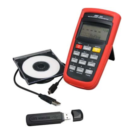
OPERATING INSTRUCTIONS
MODEL TMD SERIES
SOFTWARE
and
USB/Wireless DRIVER
V1. 011008
1492-00800UW-02
Install USB Driver:
For WINDOWS VISTA_XP
_2000 and USB Driver's
Installation
1. Connect meter to PC with USB
cable. Following dialogue box will
appear automatically. Please
select "Install USB [for
WINDOWS7_VISTA_
XP_2000"to install.
2. Installation.
Install PC software:
1. Put the disk in the disk drive.
Following dialogue box will
appear automatically. Please
execute the "autorun.exe" if it
does not appear.
Button explanations
2.
Single Meter [Wireless & Line] :
Install pc software for Single
Meter.
Multi Meter [Wireless & Line] :
Install pc software for Multi
Meter.
INSTALL USB driver (for
WINDOWS 7_
VISTA_XP_2000): Please refer
to the METER and USB
DRIVER'S
Instruction Manual: Operation
instruction manual.
EXIT: Exit install program.
Single / Multi Meter installation
window.
Advertisement

Subscribe to Our Youtube Channel
Related Manuals for Amprobe TMD Series


Summary of Contents for Amprobe TMD Series
- Page 1 Single / Multi Meter installation OPERATING INSTRUCTIONS Install USB Driver: Install PC software: window. For WINDOWS VISTA_XP MODEL TMD SERIES _2000 and USB Driver’s 1. Put the disk in the disk drive. Following dialogue box will Installation SOFTWARE appear automatically. Please 1.
- Page 2 4. In this window, you see the number of the port 3. Click “Continue”. Check CONNECTION PORT selected by system auto manically. You can 1. StartControl PanelPerformance and change it. Please write down the port number, it Maintenance. will be needed for manual connection. 4.
- Page 3 Set meter ID and CH (Only for wireless 5. Explanations of comments Description of “Single Me- models) Data Download ter“ PC software Download the saved data from the meter. (Only for save/data log function mode) 5.1 File 1. Following window comes up automatically after 6.
- Page 4 Sound of Hi/Lo limit setting Start data logger Environment selection settings dia- Graphic dialog box. : Click this button to bring log box. up “Log Setup” window. Click data folder icon on the right Interval setting and select sound effect. (Only use WAVE format).
- Page 5 I. The barograph and number are Received 8. USER LINEAR OPERATION To export data stored in meter to PC. Signal Strength Indicator (RSSI). Only available for meters with save/data RSSI >= 60 signal is better (in green log function. range).
-
Page 6: Wireless Features
Wireless Features: Frequency range: 910~920MHz 868.1~868.5MHz Current consumption: Less than 1mA. Transmission distance: 25M of sight distance without magnetic interference. FEDERAL COMMUNICATIONS COMMISSION This device complies with Part 15 of the FCC Rules. Operation is subject to the following two conditions: (1) this device may not cause harmful interference, and (2) this device must accept any interference received, including interference that may cause undesired opera-... - Page 7 2. “New ”: Start with new project Description of Multi-Meter PC ( First use ) 4-2. Please follow wizard configu- ration software 2-1 System will search free chan- nel, please wait. Multi Wireless communication Note: Please insert the Dongle af- ter SW installation.
- Page 8 5-2. :Start recording channel’s data and measuring values into txt file. 7. Dropdown menu 5-3.2 Connection status dialogue Display the connection status of 7.1 Clear All : clear List & chart each meter. to empty 7.2 Setup : Set Hi & Lo setting value to be blinking when they are over setting values.
- Page 9 Description of 8. Dropdown menu 3.“Comport search . Record data Multi Lines PC Software Insert USB to PC’s USB port Start recording channel’s data and measuring values into txt 1. Enter start page. file. 8.1 Clear All : clear List & chart Please insert USB cable with me- to empty ter, PC software will auto detect...
- Page 10 10. Y axis setting for each PS: The data displayed was list by connecting sequence, instead channel. of ID NO. First connecting in- strument might not be ID 01. Before play must to check meter power on, if show message err may be meter Precision : Y axis resolution setting power off or meter has not AUTO Y Scale ON/ OFF : Select Au-...
- Page 11 Step2. Choose the Advanced of the red frame as Comport Confirmation the illustration blow Procedure 1. Confirm to see if the port (COM&LPT1) of PC is assigned to the meter like the following illus- tration, but it could be other Comport not COM6.
Need help?
Do you have a question about the TMD Series and is the answer not in the manual?
Questions and answers