Table of Contents
Advertisement
Quick Links
PS1000-TF2Z054EN
ORIGINAL INSTRUCTIONS
Instruction Manual
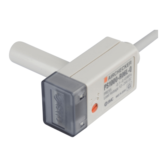
Air Checker: Electronic Pressure Switch
PS1000 / PS1100 / PS1200
The intended use of the compact pressure switch is to measure, monitor
and display pressure and provide an output signal.
1 Safety Instructions
These safety instructions are intended to prevent hazardous situations
and/or equipment damage. These instructions indicate the level of
potential hazard with the labels of "Caution," "Warning" or "Danger."
They are all important notes for safety and must be followed in addition
*1)
to International Standards (ISO/IEC)
, and other safety regulations.
*1)
ISO 4414: Pneumatic fluid power - General rules relating to systems.
ISO 4413: Hydraulic fluid power - General rules relating to systems.
IEC 60204-1: Safety of machinery - Electrical equipment of machines.
(Part 1: General requirements)
ISO 10218-1: Robots and robotic devices - Safety requirements for
industrial robots - Part 1: Robots.
• Refer to product catalogue, Operation Manual and Handling
Precautions for SMC Products for additional information.
• Keep this manual in a safe place for future reference.
Caution indicates a hazard with a low level of risk which, if
Caution
not avoided, could result in minor or moderate injury.
Warning indicates a hazard with a medium level of risk
Warning
which, if not avoided, could result in death or serious injury.
Danger indicates a hazard with a high level of risk which, if
Danger
not avoided, will result in death or serious injury.
Warning
• Always ensure compliance with relevant safety laws and
standards.
• All work must be carried out in a safe manner by a qualified person in
compliance with applicable national regulations.
• This product is class A equipment intended for use in an industrial
environment. There may be potential difficulties in ensuring
electromagnetic compatibility in other environments due to conducted
or radiated disturbances.
• Refer to the operation manual or catalogue on the SMC website (URL:
https://www.smcworld.com) for more safety instructions.
2 Specifications
2.1 General specifications
Model No.
PS1000
PS1100
PS1200
Pressure ≥
Pressure ≤ Set pressure: ON
Switch output
Set pressure:
ON
Max. operating
1 MPa
500 kPa
pressure
Setting pressure
-0.1 to 0.45
-0.1 to 0.4
-100 to 0
range
MPa
MPa
Applicable fluids
Air, non-corrosive gas, non-flammable gas
Indicator light
Switch ON: Red LED turns ON
Temp.
±3% F.S.
characteristics
Repeatability
±1% F.S.
10% F.S.
Hysteresis
4% F.S. or less
or less
12 to 24 VDC ±10%,
Load voltage
ripple (p-p) 10% or less
Load current
5 to 40 mA
Leakage current
1 mA max.
Internal voltage drop
5 V max.
Operating
0 to 60°C (no condensation)
temperature range
2 MΩ or more at 500 VDC
Insulation resistance
(between live parts and case)
1000 VAC, 1 minute
Withstand voltage
(between live parts and case)
φ6 reducer
R06
Port sizes
φ1/4" reducer
R07
Weight
5 g (excluding lead wire)
Enclosure rating
IP40
Oil resistant vinyl cabtyre cable
2 cores, φ2.55, 3 m long
Lead wire
Conductor cross section 0.18 mm
Insulator O.D. 0.96 mm
Material of wetted
Sensor: Silicon, Body: PBT, O-ring: HNBR
parts
2.2 PS1000 / PS1100 switch specification
Set pressure
The switch turns ON when
the set pressure is reached
or exceeded.
The switch turns ON at the
set pressure or below.
2.3 PS1200 switch specification
Set pressure
The switch turns ON
at the set pressure or
below.
3 Installation
3.1 Installation
Warning
Do not install the product unless the safety instructions have been read
and understood.
3.2 Piping
Caution
• Before connecting piping make sure to clean up chips, cutting oil, dust
kPa
etc.
3.3 Environment
Warning
• Do not use in an environment where corrosive gases, chemicals, salt
water or steam are present.
• Do not use in an explosive atmosphere.
• Do not expose to direct sunlight. Use a suitable protective cover.
• Do not install in a location subject to vibration or impact. Check the
product specifications.
• Do not mount in a location exposed to radiant heat.
3.4 Lubrication
Caution
• SMC products have been lubricated for life at manufacture, and do not
require lubrication in service.
• If a lubricant is used in the system, use turbine oil Class 1 (no additive),
ISO VG32. Once lubricant is used in the system, lubrication must be
continued because the original lubricant applied during manufacturing
will be washed away.
2
4 Wiring
4.1 Wiring
• Connections should be made with the power supply turned OFF.
• Use a separate route for the product wiring and any power or high
voltage wiring. Otherwise, malfunction may result due to noise.
• Incorrect wiring may cause damage to the pressure switch, breakdown
and malfunction. Confirm the colour of the wires with the operation
manual before wiring.
• Wiring applying repeated bending and tensile stress to the lead wire
can break the circuit.
• The recommended bend radius of the lead wire is 6 times the outside
diameter of the sheath, or 33 times the outside diameter of the
insulation material, whichever is larger.
• Avoid defective insulation (crossed lines with other circuit, ground fault,
defective insulation between terminals, etc.) with the wiring.
Excessive current can flow through the pressure switch, which may
cause damage.
• If the pressure switch is turned on with no load connected to the switch,
over current will flow, causing the pressure switch to break instantly.
• The pressure switch has no reverse connection protection for the
brown (+) and blue (-) of the power supply line.
• Do not exceed the maximum allowable load (24 VDC,40 mA) specified.
4.2 Circuit Diagram
4 Wiring (continued)
4.3 Wiring diagram
Example of connection to a PLC (sequence controller).
(Source Input type)
(Sink Input type)
5 Setting
• Adjust the calibration adjustment to set the ON pressure.
• Rotate clockwise to increase the set pressure. For setting vacuum
pressure rotate anticlockwise.
• For setting, use a flat blade screwdriver suitable for a trimmer. Rotate
lightly to adjust.
• The rotation angle of the trimmer is 220°.
There is a stop provided to prevent the trimmer from rotating beyond
its limits. Rotation beyond the limits can damage the trimmer. Adjust
the trimmer gently within the rotation angle.
High
High
vacuum
pressure
Pressure
setting trimmer
Caution
• Do not use a large screwdriver as this may damage the trimmer groove.
• Gently turn the trimmer and do not exceed the trimmer adjustment
range.
5.1 Hysteresis
Hysteresis is the pressure difference between the ON and OFF pressure.
The set pressure is the pressure selected to switch from OFF to ON.
Setting
pressure
Atmospheric
pressure
6 How to Order
Refer to the operation manual or catalogue on the SMC website (URL:
https://www.smcworld.com) for How to order information.
Page 1 of 2
Advertisement
Table of Contents

Related Manuals for SMC Networks PS1000


Summary of Contents for SMC Networks PS1000
- Page 1 • Use a separate route for the product wiring and any power or high 2.2 PS1000 / PS1100 switch specification Pressure Danger indicates a hazard with a high level of risk which, if setting trimmer voltage wiring.
- Page 2 PS1000-TF2Z054EN 7 Outline Dimensions Refer to the operation manual or catalogue on the SMC website (URL: https://www.smcworld.com) for Outline Dimensions. 8 Maintenance 8.1 General Maintenance Caution • Not following proper maintenance procedures could cause the product to malfunction and lead to equipment damage.
Need help?
Do you have a question about the PS1000 and is the answer not in the manual?
Questions and answers