
Related Manuals for SMC Networks PF3W711


Summary of Contents for SMC Networks PF3W711
- Page 1 No.PF※※-OMM0005-N PRODUCT NAME Digital Flow Switch (Integrated display type) MODEL / Series / Product Number PF3W7##...
-
Page 2: Table Of Contents
Table of Contents Safety Instructions Model Indication and How to Order Summary of Product parts Definition and terminology Mounting and Installation Installation Piping Wiring Flow Setting Function Setting Default settings F1 Setting of OUT1 F2 Setting of OUT2 F3 Response time setting F10 Selection of sub screen F20 Setting of external input F22 Setting of analogue output... -
Page 3: Safety Instructions
Safety Instructions These safety instructions are intended to prevent hazardous situations and/or equipment damage. These instructions indicate the level of potential hazard with the labels of "Caution", "Warning" or "Danger". They are all important notes for safety and must be followed in addition to International Standards (ISO/IEC) and other safety regulations. - Page 4 Safety Instructions Caution 1.The product is provided for use in manufacturing industries. The product herein described is basically provided for peaceful use in manufacturing industries. If considering using the product in other industries, consult SMC beforehand and exchange specifications or a contract if necessary. If anything is unclear, contact your nearest sales branch.
- Page 5 Operator This operation manual is intended for those who have knowledge of machinery using pneumatic equipment, and have sufficient knowledge of assembly, operation and maintenance of such equipment. Only those persons are allowed to perform assembly, operation and maintenance. Read and understand this operation manual carefully before assembling, operating or providing maintenance to the product.
- Page 6 Caution ■Do not touch the terminals and connectors while the power is on. Otherwise electric shock, malfunction or damage to the product can result. ■Do not touch the piping or its connected parts when the fluid is at high temperature. It may lead to burnt.
- Page 7 ●Product handling Installation Tighten to the specified tightening torque. If the tightening torque is exceeded the mounting screws, brackets and the product can be broken. Insufficient torque can cause displacement of the product from its proper position and the looseness of the mounting screws. (Refer to "Mounting and Installation"...
- Page 8 Wiring Do not pull the lead wires. In particular, never lift a product equipped with fitting and piping by holding the lead wires. Otherwise damage to the internal parts can result, causing malfunction or disconnection from the connector. Avoid repeatedly bending, stretching or applying a heavy object or force to the lead wire. Repetitive bending or tensile stress can cause the sheath of the wire to peel off, or break the wire.
- Page 9 Environment Do not use the product in an environment that is constantly exposed to the splash of water. Otherwise failure or malfunction can result. Take measures such as using a cover. Do not use the product in an environment where corrosive gases or fluids could be splashed. Otherwise damage to the product and malfunction can result.
- Page 10 Adjustment and Operation Connect a load before turning the power supply on. Do not short-circuit the load. Although error is displayed when the product load has a short circuit, generated over current lead to cause the damage of the product. Do not press the setting buttons with a sharp pointed object.
- Page 11 Handling of flow adjustment valve When flow is adjusted with the flow adjustment valve, do not apply excessive force to rotate it. This can damage the valve mechanism. When fixing the valve of the flow adjustment valve, do not apply excessive force to rotate the fixing knurl. This can damage the knurl and valve mechanism.
-
Page 12: Model Indication And How To Order
Model Indication and How to Order ●Metal piping -11- No.PF※※-OMM0005-N... - Page 13 ●Polyvinyl chloride piping -12- No.PF※※-OMM0005-N...
- Page 14 Bracket ZS-40-L Taptite screw for PF3W740 (3 x 8), 4 pcs. ZS-40-M Taptite screw for PF3W711 (4 x 10), 4 pcs. Lead wire with M8 connector ZS-40-A Lead wire length: 3 m : 2 brackets are necessary if using the type with flow rate adjustment valve. Bracket cannot be mounted onto the 250 L/min type.
-
Page 15: Summary Of Product Parts
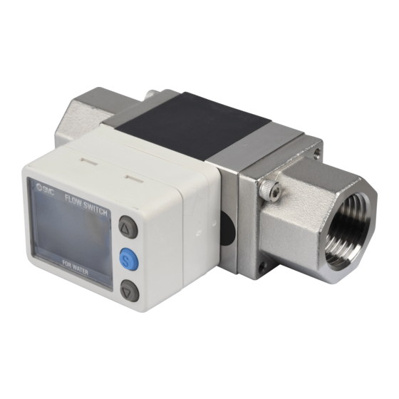
Summary of Product parts Body DC(+) OUT2 DC(-) OUT1 Element Description Connector Connector for electrical connections. Lead wire with M8 connector Lead wire to supply power and transmit output signals. Piping port Port to connect the fluid inlet at IN and fluid outlet at OUT. Bracket Bracket for mounting the product. -
Page 16: Definition And Terminology
■Definition and terminology Terms Meaning The total amount of fluid that has passed through the device. If an instantaneous flow of Accumulated flow 10 L/min continues for 5 minutes, the accumulated flow will be 10 × 5 = 50 L. Accumulated flow A function to reset the accumulated flow to zero by using an external signal. - Page 17 Terms Meaning Operating pressure Pressure range in which product is operable. range Operating temp. range Ambient temperature range in which product is operable. Part in contact with A part that comes into physical contact with the fluid. fluid (wetted part) The condition in which the digital display turns off and the current consumption is Power saving mode reduced.
-
Page 18: Mounting And Installation
Mounting and Installation Installation Use the product within the specified operating pressure and temperature range. Proof pressure could vary according to the fluid temperature. Check the characteristics data for operating pressure and proof pressure. Mounting Never mount the product in a location where it will be used as a support. Mount the product so that the fluid flows in the direction indicated by the arrow on the side of the body. -
Page 19: Installation
8 mounting screws. Bracket thickness is approx. 1.5 mm. Refer to the outline dimension drawing (page 84) for mounting hole sizes. Bracket mounting (PF3W711) Mount the product (with bracket) using the mounting screws supplied (M5 x 4 pcs.). The thickness of the bracket plate is approx. - Page 20 (page 84) for mounting hole dimensions. The self tapping screws should not be re-used. Direct mounting (PF3W711/721) Mount using the self tapping screws (nominal size: 4.0 x 4 pcs.) for installation. The tightening torque must be 1.0 to 1.2 Nm.
-
Page 21: Piping
■Piping When connecting piping to the product, a spanner should be used on the metal piping attachment only. Using a spanner on other parts may damage the product. In particular, do not let the spanner come into contact with the M8 connector. The connector can be easily damaged. - Page 22 Caution The product body is made of resin. The installation and piping of the product must satisfy the following requirements. This may cause damage, breakage and/or water leakage of the product. •No load should be directly applied to the product. •Do not install piping to the product with a misalignment.
- Page 23 How to adjust the flow rate (when a flow adjustment valve is mounted) (1) Rotate the knob of the valve to adjust the flow rate to the target value. (2) Be sure to confirm that there is no fluid leakage generated after adjustment. (When fluid leakage is generated, open and close the valve several times for re-adjustment, and confirm that there is no fluid leakage.) (3) Tighten the lock ring to fix the valve as necessary.
-
Page 24: Wiring
■Wiring Wiring of connector Connections should only be made with the power supply turned off. Use separate routes for the Flow switch wiring and any power or high voltage wiring. Otherwise, malfunction may result due to noise. Ensure that the FG terminal is connected to ground when using a commercially available switch-mode power supply. - Page 25 Examples of Internal Circuit and Wiring NPN 2 Output type PNP 2 Output type PF3W7 -A(T)- PF3W7 -B(T)- Maximum 28 V, 80 mA Maximum 80 mA Internal voltage drop 1 V or less Internal voltage drop 1.5 V or less NPN + Analogue output type PNP + Analogue output type PF3W7...
- Page 26 Example of wiring for accumulated pulse output NPN 2 output type PF3W7 -A(T)- NPN + Analogue output type PF3W7 -C(T)- PF3W7 -D(T)- NPN + External input type PF3W7 PNP 2 output type PF3W7 -B(T)- PNP + Analogue output type PF3W7 -E(T)- PF3W7 -F(T)-...
-
Page 27: Flow Setting
Flow Setting Measurement mode The mode in which the flow is detected and displayed, and the switch function is operating. This is the basic operating mode; other modes should be selected for set-point and other function setting changes. : The outputs will continue to operate during setting. : If a button operation is not performed for 30 seconds during the setting, the display will flash (This is to prevent the setting from remaining incomplete if, for instance, an operator were to leave during setting). - Page 28 Default settings When the flow exceeds the set value, the switch will be turned ON. When the flow falls below the set value by the amount of hysteresis or more, the switch will be turned OFF. If the operation shown the below is acceptable, please keep this setting. Refer to the following pages for how to change the settings.
- Page 29 <Operation of the set value change > (3 step setting mode) 1. Press the button in measurement mode to display set values. 2. [P_1] or [n_1] and the set value are displayed alternately. 3. Press the button to change the set value. button is to increase and the button is to decrease the set value.
-
Page 30: Function Setting
Function Setting Function selection mode In measurement mode, when the button is pressed for 2 seconds or longer, [F 1] is displayed. This [F ] indicates the mode for changing each functional setting. Press the button for 2 seconds or longer to return to measurement mode. The function number is increased and decreased by the buttons. -
Page 31: Default Settings
■Default settings Page Item Default setting [ oU1] Output mode (OUT1) HYS] Hysteresis mode Page [ 1ot] Switch operation (OUT1) 1_P] Normal output Page 50% of maximum rated flow 2 . 00] 2.00 L/min (4 L type) 8 . 0] 8.0 L/min (16 L type) [ P_1] Set value (OUT1) 20 . -
Page 32: F1 Setting Of Out1
■[F 1] Setting of OUT1 The output mode of OUT1 can be selected. <Flowchart of functions> 1. Selection of output mode Window Accumulated Accumulated Hysteresis comparator output pulse output ACCUMU 2. Setting of switch operation 1_P/1_N (Page 32) (Display type) Setting of Add/dEC (Page 34) - Page 33 <Operation> 1. Selection of output mode Press the button in function selection mode to display [F 1] on the main screen. The sub screen displays [oUt1] and the currently set output mode alternately. Press the button. Sub screen Press the button to select the output mode.
- Page 34 3. Input of set values a. When hysteresis output mode is selected. The sub screen displays the set value. Change it with the buttons. (When reversed output is selected, the main screen displays [n_1].) Press the button to confirm. Move on to the setting of hysteresis. The sub screen displays the hysteresis value.
- Page 35 c. When accumulated output mode is selected. Selection of accumulated increment or decrement Sub screen Press the button to select. (Continued) -34- No.PF※※-OMM0005-N...
- Page 36 Press the button to confirm. Move on to the input of set values. When accumulated increment is selected. When accumulated decrement is selected. (When the reversed output is (When the reversed output is selected, the main screen selected, the main screen displays [n1AH].) displays [n1dH].) Setting of the first...
- Page 37 4. Selection of display colour Display colour can be set to change depending upon the status of OUT1. Sub screen Press the button to select the display colour. Press the button to confirm. Return to the function selection mode. 5. Completed [F 1] Setting of OUT1 is completed.
- Page 38 ○List of output modes : If hysteresis or window comparator mode is selected and there is an unstable flow condition (due to fluid pulsation, for example), unstable output operation can result. In such situations, keep sufficient margin between the set values and confirm that the output operation stabilizes. : When the accumulated pulse output is selected, the output display will turn off.
- Page 39 : If hysteresis or window comparator mode is selected and there is an unstable flow condition (due to fluid pulsation, for example), unstable output operation can result. In such situations, keep sufficient margin between the set values and confirm that the output operation stabilizes. : When the accumulated pulse output is selected, the output display will turn off.
-
Page 40: F2 Setting Of Out2
■[F 2] Setting of OUT2 The output mode of OUT2 can be selected. The display colour is defined by OUT1 and cannot be changed with any OUT2 settings. <Flowchart of functions> With temperature sensor 1. Selection of output mode Window Accumulated Accumulated Window... - Page 41 <Operation> 1. Selection of output mode Press the button in function selection mode to display [F 2] on the main screen. The sub screen displays [oUt2] and the currently set output mode alternately. : If OUT2 is not provided, the display will be [---]. Press the button.
- Page 42 3. Input of set values a. When hysteresis output mode is selected. The sub screen displays the set value. Change it with the buttons. (When reversed output is selected, the main screen displays [n_2].) Press the button to confirm. Move on to the setting of hysteresis. The sub screen displays the hysteresis value.
- Page 43 c. When accumulated output mode is selected. The setting of Add/dEC is linked to the setting of OUT1, and can not be selected. (Refer to page 34.) When accumulated increment is selected When accumulated decrement is selected at the OUT1 setting. at the OUT1 setting.
- Page 44 d. When hysteresis mode for fluid temperature is selected. The sub screen displays the set value. Change it with the buttons. (When the normal output is selected, the main screen displays [ tP].) Press the button to confirm. Move on to the setting of hysteresis. The sub screen displays the set value.
- Page 45 ○List of output modes for fluid temperature -44- No.PF※※-OMM0005-N...
-
Page 46: F3 Response Time Setting
■[F 3] Response time setting The response time of the switch output can be set. Appropriate setting of the response time can prevent the switch output from chattering. <Operation> Press the button in function selection mode to display [F 3] on the main screen. The sub screen displays [RES] and the current set value alternately. -
Page 47: F10 Selection Of Sub Screen
■[F10] Selection of sub screen The display shown on the sub screen during measurement mode can be set. Switch point value display: Displays the set value for switch point of OUT1. (The set value for the switch point of OUT2 can not be displayed.) Accumulated value display: Displays the accumulated value of OUT1. - Page 48 <Example of display of sub screen> -47- No.PF※※-OMM0005-N...
- Page 49 <Example of display of sub screen (continued)> -48- No.PF※※-OMM0005-N...
- Page 50 <Example of display of sub screen (continued)> The maximum (peak) and minimum (bottom) flow from when the power is supplied to this moment is detected and updated. Pressing the buttons for 1 second clears the peak and bottom values. If the external input is available, the values can also be reset by external input. (Refer to [F20] Setting of external input on page 50.) The name of piping line at which the product is installed can be displayed.
-
Page 51: F20 Setting Of External Input
■[F20] Setting of external input This function can be used only when the optional external input is present. The accumulated value, peak value and bottom value can be reset remotely. Accumulated value external reset: A function to reset the accumulated value when an input signal is applied. -
Page 52: F22 Setting Of Analogue Output
■[F22] Setting of analogue output This function can be used only when the optional analogue output is present. If the optional temperature sensor is fitted, the analogue output of fluid temperature can be selected. The flow that generates the output voltage (= 5 V) or output current (= 20 mA) at the span side of analogue output can be variable. - Page 53 Use the buttons to enter the flow value that will generate full span analogue output (5 V or 20 mA). The Sub screen entered flow value can be in the range: 10% of maximum , to the upper display limit. rated flow Press the button to confirm.
-
Page 54: F30 Storing Of Accumulated Flow
■[F30] Storing of accumulated flow The default setting is not to store the accumulated flow when the power supply is turned off. This function enables the accumulated flow value to be stored in permanent memory every 2 or 5 minutes. The maximum writable limit of the memory device is 1 million cycles, which should be taken into consideration. -
Page 55: F80 Setting Of Power Saving Mode
■[F80] Setting of power saving mode The display can be turned off to reduce power consumption. (About 12%) This function is to turn to power saving mode when a button operation is not performed for 30 seconds. While the display is off, the decimal points of the main screen will flash. In the default setting, power saving mode is OFF (normal mode). -
Page 56: F81 Setting Of Security Code
■[F81] Setting of security code The security code can be entered while the keys are locked. For the key-lock function, refer to page 61. In the default setting, security code entry is not necessary. <Operation> Press the button in function selection mode to display [F81] on the main screen. The sub screen displays [PiN] and the current set value alternately. -
Page 57: F82 Input Of Line Names
■[F82] Input of line names The name of a line can be input. (Up to 6 English characters and/or numbers) The sub screen setting needs to be changed to show line names. (Refer to [F10] Selection of display of sub screen on page 46.) <Operation>... -
Page 58: F90 Setting Of All Functions
■[F90] Setting of all functions All functions can be set one after the other, without having to select each one separately from the function selection mode. <Operation> Press the button in function selection mode to display [F90] on the main screen. Press the button. -
Page 59: F98 Output Check
■[F98] Output check The output check can be turned on irrespective of flow conditions so that the circuit wiring can be checked. For the analogue output type, when ON the output will be 5 V or 20 mA, and when OFF 1 V or 4 mA. <Operation>... -
Page 60: F99 Reset To The Default Settings
■[F99] Reset to the default settings The factory default values can be restored. <Operation> Press the button in function selection mode to display [F99] on the main screen. Press the button. Sub screen Press the button to display "ON". : To return to measurement mode without changing any settings press the button for 2 seconds or longer. -
Page 61: Other Settings
Other Settings ●Reset of the accumulated flow When the accumulated value display is selected, the accumulated value can be reset. <Operation> While the accumulated value is displayed, press the buttons simultaneously for 1 second or longer. ●Reset of the peak value When the peak value display is selected, the peak value can be reset to zero. - Page 62 ●Key-lock function This function is to prevent errors occurring due to such things as set values being accidentally changed. While the keys are locked, it is possible to view the set values on the sub screen. <Operation with keys locked> Simple check of set values If the button is pressed, [LoC] is displayed on the sub screen for approximately 1 second.
- Page 63 4. Input of security code (3 digit setting) The hundreds digit starts flashing. Press the button to change the set value. Press the button to make the next value to the right flash. (If the button is pressed on the far right digit, the hundreds digit will flash.) After the setting is complete, press the button continuously for...
-
Page 64: Maintenance
Maintenance How to reset the product after a power cut or when the power has been unexpectedly removed The settings of the product are retained from before the power cut or de-energizing. The output condition also recovers to that before the power cut or de-energizing, but may change depending on the operating environment. -
Page 65: Troubleshooting
Troubleshooting Troubleshooting Applicable Flow switch: PF3W7 series If an operation failure occurs with the product, use the chart below to find out the cause of problem. If a cause applicable to the failure cannot be identified and normal operation can be recovered by replacement with a new product, this indicates that the product itself was faulty. - Page 66 Fault Detail Possible cause Item to check Recommended action Even though Operation of Open the flow adjustment Incorrect the flow rate pump while the Check the condition of the flow valve slightly, and let the display is zero, it is flow adjustment adjustment valve and pump.
- Page 67 Fault Detail Possible cause Item to check Recommended action Check if the brown wire DC(+), blue Incorrect wiring wire DC(-), black wire(OUT1) and white Correct the wiring. Improper No reaction wire(OUT2) are connected correctly. operation to the of the When the external input is external Confirm whether the input line is external...
- Page 68 Error indication function Error Name Display Type Troubleshooting OUT1 A load current of 80 mA or more is Turn the power off and over current error flowing to the switch output (OUT1). remove the cause of the over current. Then turn the power OUT2 A load current of 80 mA or more is on again.
-
Page 69: Specification
Specification ■Specifications Specifications of body (Metal attachment) Model PF3W704 PF3W720 PF3W740 PF3W711 PF3W721 1 Water and ethylene glycol solution with a viscosity of 3mPa•s (3 cP) or less Applicable fluid Detection method Karman vortex Rated flow range 0.5 to 4 L/min... - Page 70 Model PF3W704 PF3W720 PF3W740 PF3W711 PF3W721 Response 0.5 s/1 s/2 s 6 time Analogue Output voltage: 1 to 5 V, Output impedance: 1 kΩ Voltage output output Output current: 4 to 20 mA Current output Maximum load impedance: 300 Ω for 12 VDC, 600 Ω for 24 VDC...
- Page 71 Model PF3W704 PF3W720 PF3W740 PF3W711 PF3W721 Flow switch 210 g 260 g 410 g 720 g 890 g only With temperature 285 g 335 g 530 g 860 g 1075 g sensor With flow adjustment 310 g 360 g 610 g...
- Page 72 Specifications of body (Vinyl chloride piping) PF3W721 Model PF3W711 1 Applicable fluid Water and ethylene glycol solution with a viscosity of 3mPas(3 cP) or less Detection method Karman vortex 30 to 350 L/min Rated flow range 10 to 100 L/min...
- Page 73 PF3W721 Model PF3W711 Variable Hysteresis Voltage free input of 0.4 V or less (reed or solid state type) for 30 ms or longer External input 2-screen display (Main screen: 4-digit, 7-segment, 2-colour; red/green, Display method Sub screen: 6-digit, 11-segment, White) Display updating frequency 5 times/sec.
- Page 74 Flow specification of the specified order (flow unit: gal) Model PF3W704 PF3W720 PF3W740 PF3W711 PF3W721 0.13 to 1.06 0.53 to 4.23 1.3 to 10.6 2.6 to 26.4 13 to 66 Rated flow range gal/min gal/min gal/min gal/min gal/min 0.09 to 1.45 0.45 to 5.81...
- Page 75 ●Applicable fluids of vinyl chloride piping tube The material and fluids compatibility check list Chemical Compatibility Ammonium hydroxide ammonium hydroxide 3 Isobutyl alcohol isobutyl alcohol 12 ○ Isoproply alcohol isoproply alcohol Hydrochloric acid 2 ○ Concentration 30% or less hydrochloric acid (Except fuming sulfuric acid) ○...
-
Page 76: Characteristics Graph
■Characteristics graph Measurable range of ethylene glycol aqueous solution (Reference value) -75- No.PF※※-OMM0005-N... - Page 77 Flow characteristics (pressure loss: without flow adjustment valve) PF3W704 PF3W720 PF3W740 PF3W711 (Metal attachment) PF3W721 (Metal attachment) -76- No.PF※※-OMM0005-N...
- Page 78 PF3W711 (Vinyl chloride piping) PF3W721 (Vinyl chloride piping) -77- No.PF※※-OMM0005-N...
- Page 79 Operating pressure and proof pressure PF3W704/720/740 PF3W704S/720S/740S PF3W721 (Metal attachment) PF3W711 (Metal attachment) PF3W711/721 (Vinyl chloride piping) -78- No.PF※※-OMM0005-N...
- Page 80 The straight piping length shall be 8 cm or longer in order to maintain ±3%F.S. of the specification. (For the 100 L/min and 250 L/min types, the piping length should be 11 cm or longer.) PF3W704 PF3W720 PF3W740 PF3W711 (Metal attachment) -79- No.PF※※-OMM0005-N...
- Page 81 PF3W721 (Metal attachment) -80- No.PF※※-OMM0005-N...
- Page 82 Vinyl chloride piping Fluid pressure has almost no effect. The straight piping length shall be 11 cm or longer in order to maintain ±3%F.S. of the specification. PF3W711/721 (Vinyl chloride piping) -81- No.PF※※-OMM0005-N...
- Page 83 Flow characteristics of the flow rate adjustment valve PF3W704S PF3W720S PF3W740S -82- No.PF※※-OMM0005-N...
-
Page 84: Analogue Output
■Analogue output Analogue output (Flow) (PF3W704/720/740) Voltage output 1.5 V Current output 4 mA 6 mA 20 mA (PF3W711) Voltage output 1.4 V Current output 4 mA 5.6 mA 20 mA (PF3W721-12/14) Voltage output 1.8 V Current output 4 mA 7.2 mA... -
Page 85: Dimensions
2.7 depth 14 PF3W704 40.6 15.2 13.6 2.7 depth 12 PF3W720 3/8, 1/2 40.6 15.2 13.6 2.7 depth 12 PF3W740 1/2, 3/4 48.6 19.2 16.8 3.5 depth 14 PF3W711 3/4, 1 57.6 Symbol Bracket dimensions Model PF3W704 PF3W720 PF3W740 PF3W711 -84- No.PF※※-OMM0005-N... - Page 86 PF3W721 Basic type Symbol Piping port size Model 39.5 3.5 depth 14 PF3W721 71.6 28.5 41.5 27.5 43.5 -85- No.PF※※-OMM0005-N...
- Page 87 PF3W704/720/740/711/721 (With temperature sensor) Temperature sensor Symbol Model PF3W704--T PF3W720--T PF3W740--T PF3W711--T PF3W704-□-□T PF3W721-F12-□T PF3W721-F14-□T -86- No.PF※※-OMM0005-N...
- Page 88 PF3W704/720/740 (With flow adjustment valve) Basic type and flow adjustment valve Symbol Q: Number of rotations Model 2.7 depth 10 19 PF3W704S 63.6 (Max. 68.6) 70.2 58.5 13.6 6 turns 2.7 depth 10 19 PF3W720S 63.6 (Max. 68.6) 74.2 62.5 13.6 6 turns 2.7 depth 10...
- Page 89 PF3W704/720/740 (With temperature sensor and flow adjustment valve) Basic type and flow adjustment valve and temperature sensor Symbol Model PF3W704S--T 81.2 69.5 67.5 PF3W720S--T 85.2 73.5 71.5 PF3W740S--T 105.5 -88- No.PF※※-OMM0005-N...
- Page 90 PF3W711-U25/PF3W721-U30 (Vinyl chloride piping) Piping port φ3.5 depth 14 φ32 25 A 57.6 φ3.5 depth 14 φ38 30 A 71.6 28.5 60.5 27.5 Bracket dimensions Piping port 25 A -89- No.PF※※-OMM0005-N...
- Page 91 Dimensions of rotating part of display Dimensions of lead wire with M8 connector (ZS-40-A) -90- No.PF※※-OMM0005-N...
-
Page 92: Made To Order
Made to Order ●Change the seal material of the wetted parts to EPDM. Refer to page for details of how to order. ●Change the material of the piping port to brass. Refer to page for details of how to order. : Not applicable to the vinyl chloride piping type. - Page 93 Revision history A: Add the product model. B: Add the product model. C: Contents are added. D: Revision. E: Contents are added. F: Contents revised in several places. G: Contents are added. H: Contents are added. I: Contents revised in several places. J: Contents are added.
Need help?
Do you have a question about the PF3W711 and is the answer not in the manual?
Questions and answers