
Related Manuals for SMC Networks PFM7 Series


Summary of Contents for SMC Networks PFM7 Series
- Page 1 No.PF※※-OMJ0006-G PRODUCT NAME Digital Flow Switch (Integrated display type) MODEL / Series / Product Number PFM7##...
-
Page 2: Table Of Contents
Table of Contents Safety Instructions Model Indication and How to Order Summary of Product parts Mounting and Installation Installation Piping Wiring Flow Setting Function Setting Default settings F0 Unit selection function F1 Setting of OUT1 F2 Setting of OUT2 F3 Operating fluid F4 Reference condition F5 Response time F6 Display mode... -
Page 3: Safety Instructions
Safety Instructions These safety instructions are intended to prevent hazardous situations and/or equipment damage. These instructions indicate the level of potential hazard with the labels of "Caution", "Warning" or "Danger". They are all important notes for safety and must be followed in addition to International Standards (ISO/IEC) and other safety regulations. - Page 4 Safety Instructions Caution 1.The product is provided for use in manufacturing industries. The product herein described is basically provided for peaceful use in manufacturing industries. If considering using the product in other industries, consult SMC beforehand and exchange specifications or a contract if necessary. If anything is unclear, contact your nearest sales branch.
- Page 5 Operator This operation manual is intended for those who have knowledge of machinery using pneumatic equipment, and have sufficient knowledge of assembly, operation and maintenance of such equipment. Only those persons are allowed to perform assembly, operation and maintenance. Read and understand this operation manual carefully before assembling, operating or providing maintenance to the product.
- Page 6 Caution ■Do not touch the terminals and connectors while the power is on. Otherwise electric shock, malfunction or damage to the product can result. ■After maintenance is complete, perform appropriate functional inspections and leak tests. Stop operation if the equipment does not function properly or there is a leakage of fluid. When leakage occurs from parts other than the piping, the product might be faulty.
- Page 7 ●Product handling Installation Tighten to the specified tightening torque. If the tightening torque is exceeded the mounting screws and brackets may damaged. If the tightening torque is insufficient, the product may be displaced and the mounting screws may come loose (Refer to page "Mounting and Installation".) Do not apply excessive stress to the product when it is mounted with a panel mount.
- Page 8 Wiring Do not pull the lead wires. In particular, never lift a product equipped with fitting and piping by holding the lead wires. Otherwise damage to the internal parts can result, causing malfunction or disconnection of the connector. Avoid repeatedly bending or stretching the lead wire, or placing heavy loads on it Repeated bending stress or tensile stress can cause damage to the sheath, or breakage of the wires.
- Page 9 Environment Do not use the product in area that is exposed to corrosive gases, chemicals, sea water, water or steam. Otherwise failure or malfunction can result. Do not use in a place where the product could be splashed by oil or chemicals. If the product is to be used in an environment containing oils or chemicals such as coolant or cleaning solvent, even for a short time, it may be adversely affected (damage, malfunction, or hardening of the lead wires) Do not use in an area where electrical surges are generated.
- Page 10 Adjustment and Operation Connect load before turning on the power. Do not short-circuit the load. Although an error is displayed when the product load is short circuited, excess current may cause damage to the product. Do not press the setting buttons with a sharp pointed object. This may damage the setting buttons.
-
Page 11: Model Indication And How To Order
Model Indication and How to Order -10- No.PF※※-OMJ0006-G... - Page 12 Option1 with lead wire and connector (2 m) with lead wire and connector (2 m) without lead wire Connecter cover (silicone rubber) Option2 without bracket with bracket with bracket (without flow adjustment valve) (with flow adjustment valve) Not applicable to bottom entry type with panel mount adapter with panel mount adapter (without flow adjustment valve)
- Page 13 Made to Order Symbol Content Page Special combination of piping directions X693 IN side: Straight Page OUT side: Bottom entry Special combination of piping directions X694 IN side: Bottom entry Page OUT side: Straight For Argon (Ar) and carbon dioxide (CO ) mixtures.
-
Page 14: Summary Of Product Parts
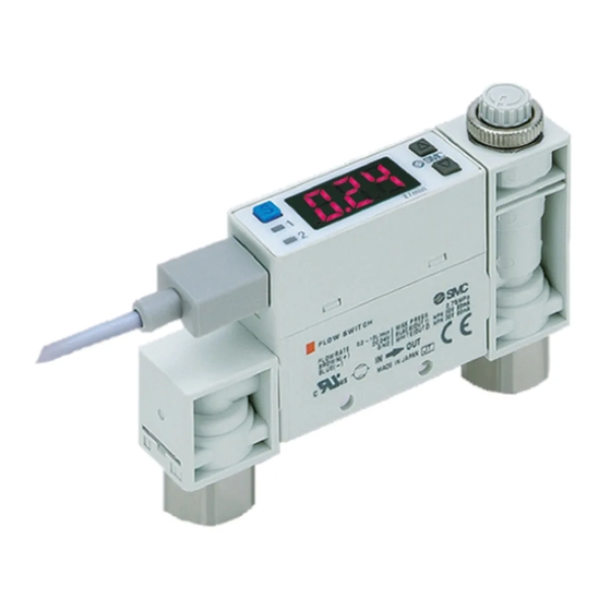
Summary of Product parts Item Description Indicates the output status of OUT1. LED is ON (Green) when OUT1 is ON. Indicator LED (OUT1) When the accumulated pulse output mode is selected, the indicator LED will turn OFF. Indicates the output status of OUT2. LED is ON (Red) when OUT2 is ON. Indicator LED (OUT2) When the accumulated pulse output mode is selected, the indicator LED will turn OFF. -
Page 15: Mounting And Installation
Mounting and Installation ■Installation Refer to the flow direction of the fluid indication on the product label for installation and piping. Panel mounting Insert Panel Mount Adapter B (supplied as an accessory) into Section A of Panel Mount Adapter A. Push Panel Mount Adapter B from behind until the display is fixed onto the panel. - Page 16 Bracket mounting Mount the bracket using the mounting screws supplied. The required tightening torque is 0.5±0.05 Nm. Without flow adjustment valve With flow adjustment valve (using ZS-33-M) (using ZS-33-MS) Install the product (with bracket) using the M3 screws (4 pcs.). Bracket thickness is approximately 1.2 mm.
-
Page 17: Piping
■Piping For the metal piping attachments Ensure that the metal piping attachments are tightened to the required torque (refer to the table below). If the tightening torque is exceeded, the product can be broken. If the tightening torque is insufficient, the fittings may become loose. -
Page 18: Wiring
■Wiring Wiring of connector Connections should only be made with the power supply turned off. Use separate routes for the product wiring and any power or high voltage wiring. Otherwise, malfunction may result due to noise. Ensure that the FG terminal is connected to ground when using a commercially available switch-mode power supply. - Page 19 Internal circuit and wiring example NPN (2 outputs) type PFM7 Max. 28 V, 80 mA Internal voltage drop: 1 V or less NPN (1 output) + Analogue (1 to 5 V) output type PFM7 NPN (1 output) + Analogue (4 to 20 mA) output type PFM7 Max.
- Page 20 PNP (2 outputs) type PFM7 Max. 80 mA Internal voltage drop: 1.5 V or less PNP (1 output) + Analogue (1 to 5 V) output type PFM7 PNP (1 output) + Analogue (4 to 20 mA) output type PFM7 Max. 80mA Internal voltage drop: 1.5 V or less E: Analogue output: 1 to 5 V Ω...
-
Page 21: Flow Setting
Flow Setting Measurement mode The mode in which the flow is detected and displayed, and the switch function is operating. This is the basic operating mode; other modes should be selected for set-point and other Function Setting changes. Switch operation When the flow exceeds the set value, the switch will turn ON. - Page 22 <Operation> : The Product outputs will continue operating during setting. 1. Press the button once in measurement mode. [P_1] or [n_1] and the set value are displayed in turn. 2. Press the button to change the set value. button is to increase and the button is to decrease the set value.
-
Page 23: Function Setting
Function Setting Function selection mode In measurement mode, press the button for 2 seconds or longer, to display [F 1]. (when using a product with unit selection function, [F 0] will be displayed). The [F ] indicates the mode for changing each Function Setting. Press the button for 2 seconds or longer in function selection mode to return to measurement mode. -
Page 24: F0 Unit Selection Function
■[F 0] Unit selection function This function is only available for products with the unit selection function. L/min or CFM (ft /min) x 10 are selectable for the displayed units. : When the products other than unit selection type are used, this function is not displayed. <Operation>... -
Page 25: F1 Setting Of Out1
■[F 1] Setting of OUT1 Set output method of OUT1. <Operation> Press the button in function selection mode to display [F 1]. Press the button. Select output mode [oU1] and the set value are displayed in turn. Press the button to select. Press the button. - Page 26 Input of set values Set flow based on setting procedure on page 21. Hysteresis mode: [P_1] Window comparator mode: [P1L] [P1H] Accumulated output mode: [P1.1] [P1.2]. ([P1.1]…Upper 3 digits, [P1.2]…lower 3 digits) Accumulated pulse output mode: Omitted : For reversed output, P becomes n. Press the button.
- Page 27 ●List of output modes : If hysteresis or window comparator mode is selected and there is an unstable flow condition (due to fluid pulsation, for example), unstable output operation can result. In such situations, keep sufficient margin between the set values and confirm that the output operation stabilizes. -26- No.PF※※-OMJ0006-G...
-
Page 28: F2 Setting Of Out2
■[F 2] Setting of OUT2 Set output method of OUT2. The display colour is linked to the setting of OUT1, and can not be set for OUT2. <Operation> Press the button in function selection mode to display [F 2]. Press the button. -
Page 29: F3 Operating Fluid
■[F 3] Operating fluid In the default setting, the PFM is intended for use with dry air or N It is necessary to change the setting when Argon (Ar) or carbon dioxide (CO ) are used. : When CO is selected, the upper limit of measurement flow range is half that of other fluids. <Operation>... -
Page 30: F4 Reference Condition
■[F 4] Reference condition Standard condition or normal condition can be selected. Standard condition (ANR) and normal condition (NOR) are defined as follows: Standard condition (ANR): 101.3kPa, 20°C, 65%RH. Normal condition (NOR): 101.3kPa, 0°C <Operation> Press the button in f function selection mode to display [F 4]. Press the button. -
Page 31: F5 Response Time
■[F 5] Response time Select the response time of the switch output. Output chattering can be prevented by setting the response time. <Operation> Press the button in function selection mode to display [F 5]. Press the button. Select response time [rES] and the set value are displayed in turn. -
Page 32: F6 Display Mode
■[F 6] Display mode Select instantaneous flow or accumulated flow to be displayed. <Operation> Press the button in function selection mode to display [F 6]. Press the button. Select display mode [dSP] and the set value are displayed in turn. Press the button to select. -
Page 33: F7 External Input
■[F 7] External input This function is available when the product includes the external input function In the default setting, when an input signal is applied, the accumulated flow value is reset to "0". : When using a product without external input function, [---] is displayed and this function cannot be set. Accumulated flow external reset: Function to reset the accumulated flow value to "0"... - Page 34 ●External input–auto shift, auto shift zero function Auto-shift and auto-shift zero are functions in which the output and display operate according to the amount of change in the instantaneous flow rate from a reference value set when an external input signal is applied.
- Page 35 The table below shows an example of the flow displayed when auto-shift zero is selected. Here, a typical condition is used as an example Operation example: Flow display before/after auto-shift zero at normal condition. Flow display [L/min] ••• Before auto-shift 10.0 ...
-
Page 36: F8 Display Resolution
■[F 8] Display resolution This function is only available for the 10 and 100 L/min types. The minimum setting unit can be changed by selecting the display resolution. In the default settings, the resolution of the 100 L/min type is 1 L/min, and the 10 L/min type is 0.1 L/min. : When a product other than the 10 L/min type and 100 L/min are used, [---] is displayed and this Function Setting is not available. -
Page 37: F9 Auto-Preset
■[F 9] Auto-preset This function is capable of calculating the approximate set value automatically based on the on-going operation. (OUT1 only) <Operation> Press the button in function selection mode to display [F 9]. Press the button. Select auto-preset [PrS] and the set value are displayed in turn. Press the button to select. - Page 38 ●In auto-preset mode, the set value can be automatically calculated and stored. Auto-preset is a function to automatically calculate the approximate set values according to the actual operating condition. If the button is pressed during measurement mode after auto-preset function is selected, the display will appear as shown in the table below.
-
Page 39: F10 Accumulated Value Hold
■[F10] Accumulated value hold The default setting is to clear the accumulated flow value when the power supply is turned off. This function enables the accumulated flow value to be stored in permanent memory every 2 or 5 minutes. The maximum writable limit of the memory device is 1 million cycles, which should be taken into consideration. -
Page 40: F11 Analogue Output Filter
■[F11] Analogue output filter This function can only be used on products with the analogue output function. The response time of the analogue output can be changed by turning off the the analogue output filter. With the filter turned off, a faster response can be obtained. : When using a product without analogue output function, [---] is displayed and this function is not available. -
Page 41: F12 Power Saving Mode
■[F12] Power saving mode In power saving mode, the display can be turned off to reduce power consumption. When the product is left for 30 seconds with no button operations, it will enter power saving mode. The decimal point flashes during operation. <Operation>... -
Page 42: F13 Security Code
■[F13] Security code A security code can be selected, which must be entered to unlock the keys when the keys are locked. Refer to key-lock function (page 46). <Operation> Press the button in function selection mode to display [F13]. Press the button. -
Page 43: F98 Setting Of All Functions
■[F98] Setting of all functions All functions can be set one after the other, without having to select each one separately from the function selection mode. <Operation> Press the button in function selection mode to display [F98]. Press the button. Setting of all functions [ALL] and the set value are displayed in turn. - Page 44 Order of Function Setting Order Function Applicable model Unit selection function Models with unit selection function Output mode (OUT1) All models Reversed output (OUT1) All models Input of set value (OUT1) All models Setting of hysteresis (OUT1) All models Display colour All models Output mode (OUT2) Reversed output (OUT2)
-
Page 45: F99 Reset To The Default Settings
■[F99] Reset to the default settings The factory default settings can be restored. <Operation> Press the button in function selection mode to display [F99]. Press the button. Reset to the default setting [ini] and the set value are displayed in turn. Press the button to select. -
Page 46: Other Settings
Other Settings ●Peak/Bottom value display The maximum (minimum) instantaneous flow, from when the power was supplied to this moment, is detected and updated. In the peak/(bottom) value display mode, the maximum (minimum) instantaneous flow can be displayed. For peak value display mode, when the button is pressed for 1 second or longer, the maximum flow will be displayed flashing, and is held. - Page 47 ●Key-lock function The key lock function is used to prevent errors occurring due to unintentional changes of the set values. If a button operation is performed while the key lock setting is ON, [LoC] is displayed for approximately 1 second. <Operation -Without security code input->...
- Page 48 <Operation -With security code input-> Locking 1. Press the button for 5 seconds or longer in measurement mode. [UnL] will be displayed. 2. Press the button to select keys lock [LoC]. 3. Press the button to store the setting and return to measurement mode. Unlocking 1.
- Page 49 How to change the security code At the time of shipment, the security code is set to [000], but this can be changed to any number. <Operation> 1. Perform the key locking procedure, followed by the first 3 steps of the key unlocking procedure 2.
-
Page 50: Maintenance
Maintenance How to reset the product after a power cut or forcible de-energizing The setting of the product will be retained as it was before a power cut or de-energizing. The output condition is also basically recovered to that before a power cut or de-energizing, but may change depending on the operating environment. -
Page 51: Troubleshooting
Troubleshooting Troubleshooting If an operation failure occurs with the product, use the chart below to find out the cause of the problem. If none of the countermeasures seem to be applicable, or a replacement product operates normally when installed, the product may be faulty. A product can be damaged by the operating environment (system configuration etc). - Page 52 Fault Status Possible cause Item to check Countermeasure Incorrect flow Check the flow range of the model Select a model with the range selected used. appropriate flow range. Incorrect Reconnect the piping with the display Check for air leakage due to loose specified tightening torque Air leakage Incorrect...
- Page 53 Fault Status Possible cause Item to check Countermeasure No reaction Buttons not when the The keys are Check if [Loc] is displayed when Release the key-lock operating buttons are locked the buttons are pressed. function. (Refer to 46) pressed The flow Loosen the lock ring, and Check the lock ring on the flow Incorrect...
-
Page 54: Error Indication
■Error indication Error Name Display Type Troubleshooting The flow has exceeded the upper limit of the Reduce the flow. flow display range. Flow error There is a flow of 5% or more in the wrong Ensure the flow is in the direction. -
Page 55: Specification
Specification ■Specifications Model PFM710 PFM725 PFM750 PFM711 Dry air, N , Ar, CO Applicable fluid (air quality class to ISO8573-1 1.1.2 to 1.6.2) Dry air, N 0.2 to 10 L/min 0.5 to 25 L/min 1 to 50 L/min 2 to 100 L/min Rated flow range 0.2 to 5 L/min... - Page 56 Model PFM710 PFM725 PFM750 PFM711 External input Voltage free input (reed switch or solid state), 30 ms or more Display accuracy ±3%F.S. max. (fluid: Dry air) Display 3 digits, 7 segment, dual colour display (red/green) Indicator LED LED is ON when output is ON OUT1: Green OUT2: Red Supply voltage 24 VDC±...
- Page 57 Piping port specifications Model 4 8 6 1/4 (5/32") (5/16") One- One- Thread type (Port size) One- One- touch touch touch touch fitting fitting fitting fitting Straight without flow 95 g 125 g 55 g adjustment valve Bottom entry without flow 105 g 135 g 65 g...
-
Page 58: Characteristics Data
■Characteristics data ●Analogue output characteristics : Analogue output at maximum rated flow rate when CO is selected is 3 [V] for the voltage output type and 12 [mA] for the current output type. Max. rated flow Max. rated flow Model Model [L/min] [L/min]... - Page 59 ●Pressure loss (at 350 [kPa]) -58- No.PF※※-OMJ0006-G...
-
Page 60: Dimensions
■Dimensions PFM7 -(N)01/(N)02/F01 -59- No.PF※※-OMJ0006-G... - Page 61 PFM7 -(N)01L/(N)02L/F01L -60- No.PF※※-OMJ0006-G...
- Page 62 PFM7 S-(N)01/(N)02/F01 -61- No.PF※※-OMJ0006-G...
- Page 63 PFM7 S-(N)01L/(N)02L/F01L -62- No.PF※※-OMJ0006-G...
- Page 64 PFM7 -F02 -63- No.PF※※-OMJ0006-G...
- Page 65 PFM7 -F02L -64- No.PF※※-OMJ0006-G...
- Page 66 PFM7 S-F02 -65- No.PF※※-OMJ0006-G...
- Page 67 PFM7 S-F02L -66- No.PF※※-OMJ0006-G...
- Page 68 PFM7 -C4/C6/C8/N7 -67- No.PF※※-OMJ0006-G...
- Page 69 PFM7 -C4L/C6L/C8L/N7L -68- No.PF※※-OMJ0006-G...
- Page 70 PFM7 S-C4/C6/C8/N7 -69- No.PF※※-OMJ0006-G...
- Page 71 PFM7 S-C4L/C6L/C8L/N7L -70- No.PF※※-OMJ0006-G...
- Page 72 Panel cut-out dimensions Flow adjustment valve +0.5 None +0.5 With flow adjustment valve 1: Piping entry direction: These are the minimum dimensions for bottom entry piping. If using straight entry piping, the material and tubing need to be taken into consideration when deciding panel cut-out spacing. 2...
- Page 73 Lead wire and connector (ZS-33-D) Connector cover (ZS-33-F) -72- No.PF※※-OMJ0006-G...
-
Page 74: Made To Order
Made to Order ●Special combination of piping direction for IN side and OUT side ports Refer to Model Indication and How to Order (page 10). PFM7 -C4/C6/C8/N7- -X693 PFM7 S-C4/C6/C8/N7- -X693 PFM7 01/02- -X693 PFM7 01/02- -X693 -73- No.PF※※-OMJ0006-G... - Page 75 PFM7 -C4/C6/C8/N7- -X694 PFM7 S-C4/C6/C8/N7- -X694 PFM7 01/02- -X694 PFM7 01/02- -X694 -74- No.PF※※-OMJ0006-G...
- Page 76 ●For a mixture of Argon (Ar) and carbon dioxide (CO The mixture ratio can be selected from Ar : CO2 = 92 : 8, 90 : 10, 80 : 20, 70 : 30 or 60 : 40. External dimensions are the same as standard. Refer to Model Indication and How to Order (page 10).
- Page 77 Details of rated flow range, display flow rate range, set flow rate range and maximum analogue output according to the gas mixture selected. Ratio Max. analogue output Model Rated flow range Display flow range Set flow range Voltage Current V max. I max.
- Page 78 Revision history A: Contents revised in several places. B: Contents revised in several places. C: Modified errors in text. D: Contents are added. E: Contents revised in several places. F: Contents revised in several places. [September 2016] G: Contents are added. [February 2017] 4-14-1, Sotokanda, Chiyoda-ku, Tokyo 101-0021 JAPAN Tel: + 81 3 5207 8249 Fax: +81 3 5298 5362 http://www.smcworld.com...
Need help?
Do you have a question about the PFM7 Series and is the answer not in the manual?
Questions and answers