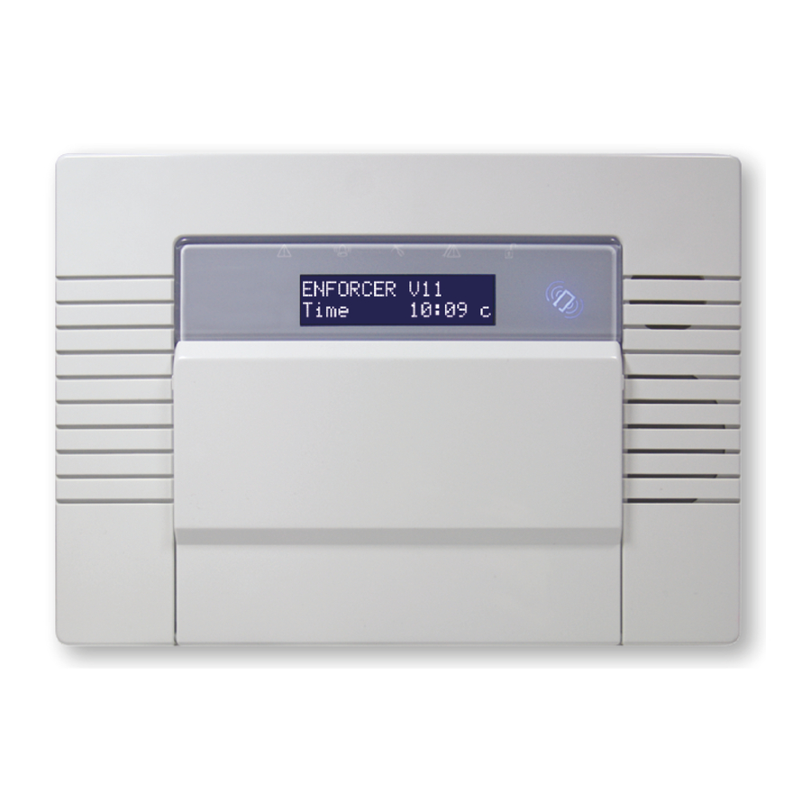
Pyronix ENFORCER V11 Installation Manual
Hide thumbs
Also See for ENFORCER V11:
- Extended user manual (40 pages) ,
- Programming manual (60 pages)
Table of Contents
Advertisement
Advertisement
Table of Contents

Related Manuals for Pyronix ENFORCER V11


Summary of Contents for Pyronix ENFORCER V11
- Page 1 ENFORCER V11 INSTALLATION GUIDE Document SAP: 102028845-01...
-
Page 2: Icons
Notes Highlights parts of the process where extra care is needed or where sections of the programming may be impacted by other options in the menus. Hints Helpful information for a smoother installation of the system. ENFORCER V11 INSTALLATION GUIDE... -
Page 3: Table Of Contents
Connecting keypads Connecting internal proximity readers Connecting external proximity readers Connecting Peripherals Wiring an external siren Wiring zones Connecting Expansion Modules Connecting a wired zone expander Connecting a wireless zone expander Connecting an output expander Certification ENFORCER V11 INSTALLATION GUIDE... -
Page 4: Introduction
• Two Way Wireless Protection • Signal Strength Indicator (SSI) • Instant Two Way Device Control • Pyronix High Security Wireless Protocol Encryption • Programmable Wireless Supervision Time • Intelligent Wireless Jamming Detection Default codes Master Manager Code: 2222 Engineer Code: 1111... -
Page 5: Specification And Warranty
F500mA 250V Bus Fuse Aux fuse F500mA 250V Aux Fuse SYSTEMS ANALYSIS: ZONES (MAX 66) Wireless Wired 4 wired (8 wired zones each) EURO-ZEM8, EURO-ZEM8+ or EURO-ZEM8+PSU Zone expansion modules 1 wireless (32 wireless zones) EURO-ZEM32-WE ENFORCER V11 INSTALLATION GUIDE... - Page 6 Please note: Compliance labelling should be removed or adjusted if non-compliant configurations are used. Technical functions for example fire, gas and flooding are not security graded as they are outside the scope of EN50131-1 and EN50131-3. ENFORCER V11 INSTALLATION GUIDE...
-
Page 7: Installation Guide
4 The panel should be mounted at least 1 metre away from any source of electrical or radio interference including but not limited to, mains consumer units, solar PV control equipment etc. 5 If cable management is an issue, a spacer is available: ENF/SPACER-WE ENFORCER V11 INSTALLATION GUIDE... -
Page 8: Inside Of The Enforcer
1. Back up battery compartment. 2. Tamper spring. 3. RS232 connection for upload/download to InSite software. 4. Communications module power connection. 5. I/O board connection. 6. The connection for a communication module to be installed. 7. Transformer connection. (15VDC) ENFORCER V11 INSTALLATION GUIDE... -
Page 9: Connecting The Control Panel Battery
On completion of wiring use tie-wraps to prevent any loose wires causing a safety hazard (material of cables tie shall be rated at least HB or better). Cables ties and hoses shall be separate for power supply cable and SELV wirings. Size of protective bonding conductors: minimum section 1.5mm². ENFORCER V11 INSTALLATION GUIDE... -
Page 10: Input/Output Board
Each keypad is addressed individually in the keypad menu, press and hold the D key on the keypad until ‘SECURITY CODE’ is displayed. Enter ‘2000’ and enter the assigned address (the first keypad that is connected should be addressed as ‘01’). Press the a key to save the data and exit. ENFORCER V11 INSTALLATION GUIDE... -
Page 11: Connecting Internal Proximity Readers
Brown and orange to 0V/GND Address 02 Brown and green to 0V/GND Address 03 Brown to 0V/GND Please note: If using the external reader as access control or entry control please refer to the peripheral instructions for connection details ENFORCER V11 INSTALLATION GUIDE... -
Page 12: Connecting Peripherals
I/O board). Note, the zone must be programmed as ‘tamper’ . The resistor value will correspond to the value selected in ‘W ’ . iRing hoiCe IMPORTANT NOTE: The external siren connected needs to be set in SCB mode unless it is a Pyronix external siren. Wiring zones ALARM TAMPER... -
Page 13: Connecting Expansion Modules
ZEM as ZEM addresses 00, 01 and 02 in the menu item ‘i ZeM’ and learn 24 nstAll zones to the system using the ‘W ’ menu. Then address a wired ZEM as ZEM 03. iReless eviCe ontRol ENFORCER V11 INSTALLATION GUIDE... -
Page 14: Connecting An Output Expander
PGM STB BELL Z33 COM +12V Z34 Please note: The above shows the I/O board connected to a EURO-OEM8R8T. If the expander is a EURO- OEM16R+PSU, the D2+ terminal must not be connected to the I/O board. ENFORCER V11 INSTALLATION GUIDE... -
Page 15: Certification
Technical documentation for the assessment of electrical and BS EN IEC 63000: 2018 electronic products with respect to the restriction of hazardous substances Compliant operation is only guaranteed when installed and operated according to the relevant installation and user manuals. ENFORCER V11 INSTALLATION GUIDE...
Need help?
Do you have a question about the ENFORCER V11 and is the answer not in the manual?
Questions and answers